Download
1 / 45
460 likes | 635 Vues
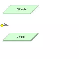
Impact of 42 Volts on Connection Systems. Prepared by : John Yurtin Staff Product Specialist August 5, 2003. Agenda. 14/42 V Electrical System Proposed Voltage Specification Vehicle Power Requirements Shock Hazard Protection Electrical Architectures

E N D
Impact of 42 Volts on Connection Systems Prepared by : John Yurtin Staff Product Specialist August 5, 2003
Agenda • 14/42 V Electrical System • Proposed Voltage Specification • Vehicle Power Requirements • Shock Hazard Protection • Electrical Architectures • What 42 Volt means to Standard Connections • 42V Impact on Electrical Contacts • Non-arcing • Connectors • Sliding contacts in Sensors • Arcing Contacts • Switches • Relays • High Power 42 Volt Connections
Automotive Electrical System History (cont)Vehicle Power Requirements Generator Peak Power of Average Passenger Vehicle (watts) w/Propulsion (HV, FC, EV) 100,000 Growth Rates: 1920-40 6%/yr 1940-70 2%/yr 1970-90 6%/yr Projected 1990-2030: excl. Proplsn 5%/yr w/Propulsion 8%/yr 40 kW 15 kW 10,000 Watts excl. Propulsion 1,000 1.8 kW 100 1920 1930 1940 1950 1960 1970 1980 1990 2000 2010 2020 2030 Year
Changing Trend In Automotive Electrical Systems 1 - 2 kW >90 kW Conventional Internal Combustion Engine and Electrical System Fuel Cell or All Electric 3 - 5 kW 45 kW - 90 kW Starting Motor Alternator Battery Engine Driven Motor/Generator Large Battery or Fuel Cell Propulsion Motors Inverter/Converter Internal Combustion Engine High Power Electrical System Hybrid Electric 5 - 45 kW Internal Combustion Engine Small Internal Combustion I.C. Engine Dominant Battery Dominant or Fuel Cell
HIGH POWER ELECTRICAL SYSTEMS HYDRO-CARBON REFORMER SYSTEMS ELECTRIC VALVE SYSTEMS ELECTRIC HVAC SYSTEMS ELECTRIC TURBO SYSTEMS FUEL CELL SYSTEMS MOBILE AC POWER SYSTEMS IMPROVED FUEL ECONOMY ELECTRIC SUSPENSION SYSTEMS ELECTRIC STEERING SYSTEMS ELECTRIC BRAKING SYSTEMS WHY 42 VOLTS?
WHY 42 VOLTS? Proposed New Electrical Loads
Impact of 42V Electrical System V42 = 3V14 P42 = P14 P42 = I 42 * V42 = I 14 * V14 3 * I42 = I14 I42 = 1/3 I14 By reducing the cable cross-section to 1/3 of original: R14 = 1/3 R42 P14loss = V14I14 P42loss = V42I42 P14loss = (I14R14) I14 P42loss = (I42R42) I42 P14loss = (I14 )2R14 P42loss = (I42 )2R42 P42loss = (1/3 I14)23R14 P42loss = 1/9 (I14 )2*3R14 P42loss = 1/3 (I14 )2*R14 = 1/3 P14loss Therefore, the cable power loss @ 42 V is 1/3 the cable power loss @ 14V.
14-Volt Electrical System 12 V Lead Acid Battery 14 V Starter/ Generator 12 V Starter 14 V Loads
14/42-Volt Electrical System 36V Battery 42V Liquid Cooled Generator 42V LOADS 14V * Includes 42 V Starter LOADS 42/14V DC-DC Converter
14/42-Volt Electrical System 42 V 36 V AGM Lead Acid or 42 V Lithium Polymer Battery 14 V Dual-Output Generator 42 V Loads 14 V Loads
High Current and High Voltage • 42 Volt systems do not necessarily mean High Current • A 42 Volt system may have small low current connections (e.g. 150 GT). In fact the higher voltage will allow for smaller connectors and wiring for the same current requirements. This is one of the advantages of 42 V systems. • 42 Volt systems will provide the support for high current devices and options as well. This is the other advantage of 42V systems. In these cases, high current connectors may be used ( e.g. Power-Pack).
21V 9V 42V 14.3V 52V 16V 58V 20V 0 0 11V 30V Proposed Voltage Specification Voltage Requirements @ 14V minimum minimum Power- max. max. dynamic voltage operating Net static overvoltage at start voltage over- Voltage (Alt/Regulator) (load dump) voltage Voltage Requirements @ 42V minimum minimum Power- max. max. dynamic voltage operating Net static overvoltage at start voltage Voltage (Alt/Regulator) over- (load dump) voltage
Safety: Shock Hazard Protection • Historically, the SAE industry standard for “Low Tension” is a nominal system voltage of 50V dc or less in vehicle electrical system. Discussions are underway to revise the upper limit to 60V dc. • IEC 479 defines safe contactlimit of 60V dc (1998) • The limiting factor for direct voltages is a shock-hazard protection limit of 60V….at low temperatures the charging voltage of the battery (a 48V string) can attain 60V. • Determining a “safe” dc voltage limit is a complex task affected by multiple variables including time, voltage, skin impedance, internal body impedance, environment, current path and an individual’s susceptibility to electrical current. Discussions are continuing to establish industry standards on both voltage limits and safe practices.
42V Impact On Electrical Contacts • NON-ARCING CONTACTS • CONNECTORS • SLIDING CONTACTS IN SENSORS • ARCING CONTACTS • SWITCHES • RELAYS
Direction For Non-Arcing Contacts • New Higher Current 42V Connections (100 Amps +) • Battery • DC-DC converter • Starter/generator • Downsized Harness Connections • Minimal downsizing for initial 14/42V systems • Significant downsizing with full 42V system - many terminals will carry under 5 Amps • Change in connector product mix • Smaller conductor size makes IDC and flex circuit connections more attractive • Changes not expected for low voltage sensors • 5V bus for sensor and signal circuits expected to remain on 42V vehicles
Challenges For Separable Connectors • Hot Plug/Disconnect • Corrosion
Hot Terminal Disconnect • 14 Volt • 22 Amps
14 Volt Corrosion • 14 Volt • 22 Amps • 3 Drops of Salt Water
Hot Terminal Disconnect • 42 Volt • 21 Amps
Hot Terminal Disconnect • 42Volt • 7 Amps
42Volt Corrosion • 42 Volt • 31 Amps • 3 Drops of Salt Water
Challenges For Separable Connectors Hot-Plugging • Hot Plugging • 14V Fuses, relays, and harness connections are often disconnected while circuit is active – small arcs can be produced • Hot plugging of 42V circuits can produce arcs with enough power to melt terminals • Arc extinguishing lengths are much longer with 42V
80 V 70 60 50 40 30 20 10 0 UArc 42 V, 21 A 1,0 mm 0,8 mm 42 V, 7 A 0,5 mm 0,3 mm 0,1 mm 14 V, 21 A Um I 1 2 3 7 8 A THS 2000 Predicted arc extinction length
42 Volt Hot Plugging • Hot Plugging can degrade the performance of terminals at current levels far below their maximum rated current 25A-rated terminal after 8A hot plug • It will take a combination of new hardware designs and system designs to minimize the effects of 42V hot plugging
42 Volt Corrosion • 42V corrosion expected to be 3 times faster than 14V corrosion, based on Faraday’s Law • New corrosion-related degradation mechanisms are possible with 42V systems Ground + 42V Corrosion after 2 min. @ 42V in 5% Saltwater
42V Corrosion • Connection degradation mechanisms from corrosion • Removed plating and substrate metal – leads to high resistance connections • Build-up of corrosion products – can lead to short circuits • Leakage current to sensor circuits - can give false signals
42 Volt Corrosion • Some existing 14V connection systems may need modified for use at 42V • Increased terminal spacing • Longer creep path distance between conductors • Less use of hygroscopic connector materials • Increased usage of environmentally sealed connectors
42V Effect On Terminal Contact Finishes • No changes to contact finishes expected • Fritting of degraded contacts usually occurs below 14V. • 42V contacts still have the potential to reach unacceptably high resistance levels if a suitable contact finish is not used • For the same Joule heating as existing 14V connectors, 42V connections with 1/3 of the current can have 9 times more resistance
42V Arcing Contacts - Switches • Most 14V switches not designed to operate at 42V • 42V switches may not be practical due to cost and size • Low current switches combined with relays expected to be more attractive • Optimum switching solutions not yet identified
42V Arcing Contacts - Relays • About 30 relays in today’s luxury cars • 14V relays not designed to withstand 42V • Product performance requirements for 42V relays not yet defined • Increased size for 42V due to larger contact gaps and arc extinguishing methods • Solid State relays not a direct replacement for EM relays • polarity sensitive • system cost impact • Sealing may be more critical
Summary • Higher voltage automotive electrical systems are here and will be on the increase • The change to 42V will have a significant effect on automotive electrical systems • New component designs and system solutions will be required
High Power 42 V Connections Prepared by : John Yurtin Staff Product Specialist August 5 , 2003
1500 Series Terminal • Electrical • 150 amps max. continuous (room temp.) • 55°C max. temperature rise at rated current • -40°C to 155°C operating temperature • 0.5 mv/Amp max. voltage drop after conditioning crimp to crimp • 0.5 m max. resistance total after conditioning crimp to crimp • 35mm² cable max. and 13mm² cable min. • Mechanical • Hand engage/disengage(no tool and <80 N) • Terminal engage force : 45 N max. • Terminal insertion force : 30 N max. • Terminal retention force : 150 N min. w/o TPA, 200 N min. w/TPA • Connection un-mating force : 160 N min. w/o CPA, 200 N min. w/CPA
2000 Series Terminal • Electrical • 200 amps max. continuous (room temp.) • 55°C max. temperature rise at rated current • -40°C to 155°C operating temperature • 0.5 mv/Amp max. voltage drop after conditioning crimp to crimp • 0.5 m max. resistance total after conditioning crimp to crimp • 50 mm² cable max. and 13mm² cable min. • Mechanical • Hand engage/disengage(no tool and <80 N) • Terminal engage force : 45 N max. • Terminal insertion force : 40 N max. • Terminal retention force : 200 N min. w/o TPA, 230 N min. w/TPA • Connection un-mating force : 450 N min. w/CPA
1500 and 2000 Series Terminals 10 vane Insert 2000 Series 8 vane Insert 1500 Series
2000 Series Inline Unsealed Connection In-line with 1 full insert
2 Way Power-Pack Connection • Current production plans for the 2000 Series connection system • Ford Think – 2 2 way sealed right angle connection • Start of production 6/02 • 2004 vehicle program – 2 way sealed right angle connection 12 vane insert 2 way connection HC 2000 200A terminal
1500 Series In-Line Connection Connector seal Same design approach as 2 way under test Cable seal Same design approach as 2 way under test Female terminal - Uses 8 vaned, silver plated BeCu insert 14.5mm wide blade Conforms to design developed for SAE/USCAR 42v standard battery TPA/Seal Retainer Same for male and female connector
Summary • High Power Connection system • Engaged and Disengaged by Hand • Sealed and Unsealed Designs • Silver Plated Terminals for Higher Temperature Environments • Hermaphrodite Terminal • Inline and Header Mating • Designed to meet SAE/USCAR Class 3 Requirements
42 V Battery Connection System Prepared by : John Yurtin Staff Product Specialist August 5, 2003
42V Battery Interface • The system incorporates a 1.80 mm by 14.5 mm plated, high conductivity blade • The system is insert molded • Side mounted connection (horizontal) • Low height profile for side mounted configuration • Mating terminal design provides 90° wire dress • Recessed terminals prevent shorts between terminals and from positive to ground • Narrow shroud opening prevents attachment of standard jumper cables • The system is designed to be sealed (sealing code 2) • Targeted continuous current is 150 Amps with 55°C temp. rise
24V Battery Connection System Application • Sealed, 2 way 42V Battery Connection Features • Make last / break first 280 sense terminal to prevent system arcing • High current blade is 14.5 mm wide and 80% conductivity material min. • High current female terminal is two piece design utilizing hertzian insert • Individually sealed connector cavities • Mechanical assist to control mate/unmate speed • Flame retardant materials • TPA & PLR for terminal retention Capabilities • Meets SAE J2622 design standard Stage of Development • Design concept complete • Prototype availability : Header available, female connector asm. available 9/03. Contact • Jim Daugherty (01)330-373-3735 fax-4147 (james.daugherty@delphi.com) Connection System- Closed Position High Current Female Terminal with Hertzian Insert Date of status: June 16, 2003