RF Cavity Design and Distribution Challenges in High Voltage Systems
This summary outlines the technical requirements and issues encountered in RF cavity design, specifically focusing on a nominal voltage of 120 kV, with a maximum preference of 180 kV. Key aspects discussed include aperture size, frequency range, and the need for optimized geometry. The challenges of signal management at BPMs and the integration of power sources like IOT amplifiers and klystrons are highlighted. Additionally, the complexity of RF distribution for multiple cavities and new actions needed for cost and physical assessments are summarized.

RF Cavity Design and Distribution Challenges in High Voltage Systems
E N D
Presentation Transcript
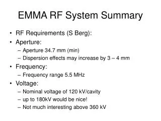
EMMA RF System Summary • RF Requirements (S Berg): • Aperture: • Aperture 34.7 mm (min) • Dispersion effects may increase by 3 – 4 mm • Frequency: • Frequency range 5.5 MHz • Voltage: • Nominal voltage of 120 kV/cavity • up to 180kV would be nice! • Not much interesting above 360 kV
RF Cavity • Optimised geometry developed (E Wooldridge): 2.1 M limit proposed in Jan07
Cavity Issues • For the baseline (120kV) cavity design looks ok. • Evanescent field not zero at the cavity flanges large signals at BPM’s (50x too large!) • Issues: • Asymmetric beam-pipe geometry • Damping e-m fields external to cavity • Moving the BPM further away • Making cavity beam pipe elliptical • Input coupler and tuning • Using cavity HOMs as BPM?
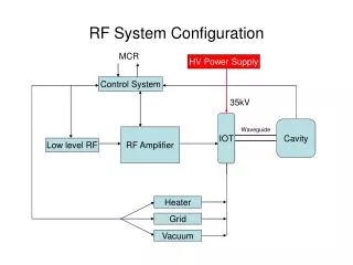
RF Distribution • Power sources identified (C Beard): • 20 kW IOT e2v integrated amplifier • 30 kW IOT Thales/CPI (non-integrated) • 160 kW Klystron e2v
RF Distribution • Integrated e2v IOT amplifier includes: • HVPS • Drive amplifier • Cooling • Local controls • Non-integrated IOT and klystron needs these separately • HVPS options: • 1 large HVPS • Baseline 30kV/5A (IOT) or 48kV/6A (Klystron) • Multiple small HVPS • Baseline 30kV/1A for each IOT • In early 2009, the SRS RF HVPS will become available: • 50kV/10A DC supply • Configured to power a modulating anode klystron • Needs modifying to power proposed IOT/klystrons • Additional costs incurred (needs to be assessed)
RF Distribution • With 19 cavities, distribution will be complicated regardless of solution adopted. • 4 cavities/IOT • 19 cavities/klystron • Distribution options: • Waveguide hybrid splitters • Waveguide adaptive couplers • Combiner cavity (requires R&D) • Individual cavity phase provided in distribution line (waveguide or coax) • LLRF cavity phase compensation provided per amplifier distribution
Distribution Issues • For the various distribution options: • Assess detailed costings • Investigate physical limitations