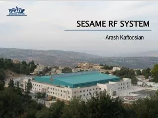
RF System Configuration
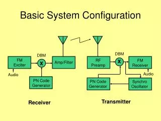
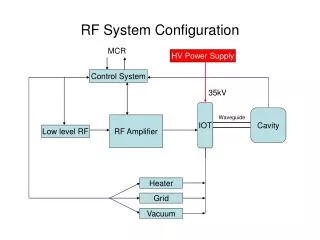
RF System Configuration. MCR. HV Power Supply. Control System. 35kV. IOT. Cavity. Waveguide. RF Amplifier. Low level RF. Heater. Grid. Vacuum. Technology used on ERLP. Capacitor bank must be sufficient to limit voltage droop. Large stored energy due to capacitor bank.

RF System Configuration
E N D
Presentation Transcript
RF System Configuration MCR HV Power Supply Control System 35kV IOT Cavity Waveguide RF Amplifier Low level RF Heater Grid Vacuum
Technology used on ERLP. Capacitor bank must be sufficient to limit voltage droop. Large stored energy due to capacitor bank. Expensive Crowbar required. Only suitable as central power supply for all IOTs. Large physical size – limited space. Old technology but reliable. Line - Commutated Solution Typical Line Commutated Power Supply with Crowbar
Thales Power Supply • Existing switch-mode technology power supply. • Significant direct cost savings. • Low stored energy – no crowbar required. • Variable output voltage – only operating at half full scale. • Large physical layout – will require dedicated building • Control system included – suitability to IOT loads needs investigation. • Only suitable as central power supply for all IOTs. • Spare components available. 9 m 6 m 2.5m 6 m Minimum building dimensions
Low Stored Energy – Crowbar not required. Capacitor chargers rated for full dc output. Switch-mode technology providing fast response time to load changes. Independent HT supply for each IOT. Compact design – will fit comfortably into a single rack. Commercial off-the-shelf components Control system needs to be developed. MCR Control DCCT Charging Supply + IOT - 50nF 35kV Charging Supply + - Heater Grid Proposed alternative solution
Thales Power Supply Existing unit used on SRS – direct cost savings. Reliable technology – available spares. Large physical size. New building required within 50m of IOTs. Utilise integrated control system – configured now for klystron technology. Single supply feeding all IOTs – lose versatility. Lambda Charging Units Prototype design being investigated. New technology – reliability unknown. Compact physical size Increase options for locating system. Relatively low cost solution using commercially available units. Independent supplies for each IOT. Control system needs to be developed. Comparison of Options Additional Issues Location of RF system and auxiliary equipment – radiation issues and performance Cable management access – Labyrinths