Download
1 / 23
230 likes | 414 Vues
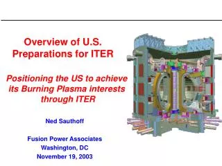
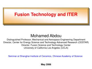
US ITER Technology Issues. Charles C. Baker Virtual Laboratory for Technology presented at the U.S. ITER Forum University of Maryland, College Park May 8, 2003. R. Aymar/ Fusion Engineering and Design 55 (2001). Fig. 1 Cutaway of ITER. T. Mizoguchi/Fusion Engineering and Design 55 (2001).

E N D
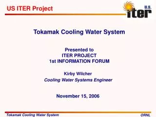
US ITER Technology Issues Charles C. Baker Virtual Laboratory for Technology presented at the U.S. ITER Forum University of Maryland, College Park May 8, 2003
R. Aymar/ Fusion Engineering and Design 55 (2001) Fig. 1 Cutaway of ITER
T. Mizoguchi/Fusion Engineering and Design 55 (2001) Fig. 1 Central solenoid model coil (CSMC) configuration (above) and fabricated modules (below) during assembly at JAERI, Naka (JA). Another TF insert coil is fabricated by Russia and tested at JAERI.
H. Tsuji et al. /Fusion Engineering and Design 55 (2001) Fig. 2 Fabrication flow of CS model coil and CS insert coil.
T. Mizoguchi/Fusion Engineering and Design 55 (2001) Fig. 3 Toroidal field model coil (TFMC) configuration (above left), internal coil structure (ICS) with LCT coil (above right) and TFMC in the TOSCA Hall at FZK, Karlsruhe (EU).
T. Mizoguchi/Fusion Engineering and Design 55 (2001) Fig. 5 Two half-sectors (above) of full-scale vacuum vessel sector (JA) before field joint and equatorial port (RF) after assembly at JAERI, Tokai (JA).
T. Mizoguchi/Fusion Engineering and Design 55 (2001) Fig. 6 Demonstration of remote welding (US).
T. Mizoguchi/Fusion Engineering and Design 55 (2001) Fig. 8 Cut-out of prototype shield blanket module for destructive examination (JA).
T. Mizoguchi/Fusion Engineering and Design 55 (2001) Fig. 10 Integrated inner divertor cassette (above left) at Sandia (US), integrated outer divertor cassette (below) at EFET (EU) and high heat flux testing of divertor target by ion beam (above right) at JAERI, Naka (JA).
T. Mizoguchi/Fusion Engineering and Design 55 (2001) Fig. 11 Overview of blanket test platform at JAERI, Tokai (JA). The 180o rail is shown in the right side. From right to left, the 180o support, the 90o support and the vehicle with the manipulator are attached to the rail.
T. Mizoguchi/Fusion Engineering and Design 55 (2001) Fig. 13 Overview of divertor test platform at ENEA, Brasimore, (EU).
R&D Resources Summary and New R&D for ITER-FEAT (from TAC-16 Progress Report-R&D, June 25-27, 2000)
R&D Resources Summary and New R&D for ITER-FEAT (from TAC-16 Progress Report-R&D, June 25-27, 2000)
R&D Resources Summary and New R&D for ITER-FEAT (from TAC-16 Progress Report-R&D, June 25-27, 2000)
Heating & Current Drive Fueling Magnets Disruption Mitigation PFC/PMI TECHNOLOGIES ARE REQUIRED TO ADVANCE SCIENCE. TOOLSDEVELOPMENT NEEDEDTO GET TO Better gyrotrons Better ion cyclotron launchers and control • Steady-state • Advanced Performance • Burning Plasmas Faster inside-launch pellets Compact torus injection tests Increased B-field/$ Improved innovative superconductor cable Fast, reliable disruption detection Fast low-Z liquid/gas injection system Lower erosion, higher heat flux PFCs Integrated PMI code SCIENCE/TECHNOLOGY PARTNERSHIP
PW-8, PW-14 and PW-14b after testing in EB1200. PW-8 HIPped One rod melted after 500 cycles at 20 MW/m2. PW-14 e-beam welded PW8, reached 24MW/m2 in EB1200 PW-14b e-beam welded PFC Testing for ITER • Development of W PFC continues to show improvement in capability and reliability (SNL) • Mixed materials (C, Be, W) erosion studies are in progress at UCSD • Tritium retention and removal studies in progress at SNL and INEL
RF Technology Highlight: The JET-EP ICRF Antenna and the High Power Prototype (HPP)
Plasma Fueling Highlights: 1. Massive Gas Puff for Disruption Mitigation - Mainline Tokamaks 2. Pellet injector in a Suitcase - Alternative Confinement Devices 3. Pellet fuelling - H-mode fuelling
Chamber Technology Achievements in FY02/03 MTOR allows experiments on MHD fluid flow in self-cooled liquid metals, and free-surface liquid walls. • Facilities were constructed and operated to address liquid breeder MHD in both free-surface and closed channels. • Sophisticated and complex computer code development is underway for 3-D modeling of fluid flow. • Established a temperature window in which a liquid wall can operate within an MFE reactor with a high exit coolant temperature for power conversion. • Explored advanced solid wall blanket concept with potential to improve the attractiveness of fusion power plants. • Obtained experimental results of the effective thermal properties of beryllium packed beds. FLIHY addresses key issues and innovative techniques for enhancing heat transfer in low-conductivity fluids in closed channel flows.
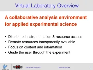
ITER provides Unique Technical Challenges for Diagnostics • Measurement requirements demand performance capability for present-day machines + alpha-particle measurement, + operation in radiation environment, presence of blankets, + reliability, calibration maintenance, + control data for machine protection. • Significant engineering design issues. Port-plug with penetrations for Thomson scattering, interferometry, etc. 2m high x 1.8m wide x 3.5m long Weight 66 tonne Side and bottom 130mm thick Front & port flange 200mm Designs by C. Walker (JCT) Equatorial port-plug concept