Fusion Technology and ITER
Fusion Technology and ITER. Mohamed Abdou Distinguished Professor, Mechanical and Aerospace Engineering Department Director, Center for Energy Science and Technology Advanced Research (CESTAR) Director, Fusion Science and Technology Center University of California Los Angeles (UCLA)

Fusion Technology and ITER
E N D
Presentation Transcript
Fusion Technology and ITER Mohamed Abdou Distinguished Professor, Mechanical and Aerospace Engineering Department Director, Center for Energy Science and Technology Advanced Research (CESTAR) Director, Fusion Science and Technology Center University of California Los Angeles (UCLA) Seminar at Shanghai Institute of Ceramics, Chinese Academy of Science May 2006
Outline • World energy needs • Fusion: Energy source for the XXI century • ITER • ITER Test Blanket • Principles of Fusion Nuclear Technology • Blanket concepts • He-Cooled Ceramic Breeder Blanket (HCBB) • Dual Coolant Lead-Lithium Concept (DCLL) • SiC/SiC Flow Channel Insert (FCI) • Liquid Walls • MHD Code Development • Summary
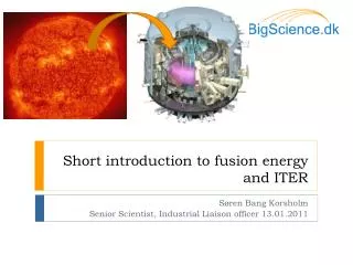
What is Nuclear Fusion? • Nuclear Fusionis the energy-producing process taking place in the core of the Sun and stars • The core temperature of the Sunis about 15 million °C. At these temperatures hydrogennuclei fuse to give Helium and Energy. The energy sustains life on Earth via sunlight
Fusion Reactions • Deuterium– from water(0.02% of all hydrogen is heavy hydrogenor deuterium) • Tritium– from lithium(a light metal common in the Earth’s crust) Deuterium + Lithium → Helium + Energy This fusion cycle(which has the fastest reaction rate) is of interest for Energy Production
Figure 1.1 Energy use (in gigajoules) vs. GDP (on a purchasing power parity basis) for selected countries on a per capita basis. Data from the International Energy Agency. Upper line indicates ratio for the US; lower line indicates ratio for Japan and several Western European countries.
Figure 1.2. Human development index vs. per capita electricity use for selected countries. Taken from S. Benka, Physics Today (April 2002), pg 39, and adapted from A. Pasternak, Lawrence Livermore National Laboratory rep. no. UCRL-ID-140773.
The World, particularly in developing countries, needs a New Energy Source • Growth in world populationand growth in energy demand from increased industrialisation/affluencewill lead to an Energy Gap which will be increasingly difficult to fill with fossil fuels • Without improvements in efficiency we will need 80%more energy by 2020 • Even with efficiency improvements at the limit of technology we would still need 40%more energy
World Energy Scene* (I) • 1) The world uses a lot of energy • Average power consumption = 13.6 TWs, or 2.2 kWs per person • World energy market ~ $3 trillion/yr (electricity ~$1 trillion/yr) • - very unevenly (OECD 6.2 kW/person; Bangladesh 0.20 kW/person; China 1.3kW/person) • 2) World energy use is expected to grow • - growth necessary to lift billions of people out of poverty • 3) 80% is generated by burning fossil fuels • climate change & debilitating pollution • - which won’t last for ever Need major new (clean) energy sources - requires new technology *See Sir Chris Llewellyn-Smith, FPA, October 11, 2005
Future Energy Use • The International Energy Agency (IEA) expects the world’s energy use to increase 60% by 2030 (while population expected to grow from 6.2B to 8.1B) - driven largely by growth of energy use and population in India (current use = 0.7 kWs/person, vs. OECD average of 6.2 kWs/person) and China (current use = 1.3 kWs/person) • Strong link between energy use and the Human Development Index (HDI ~ life expectancy at birth + adult literacy and school enrolment + gross national product per capita at purchasing power parity) – need increased energy use to lift billions out of poverty
Carbon dioxide levels over the last 60,000 years - we are provoking the atmosphere! SourceUniversity of Berne and National Oceanic, and Atmospheric Administration
Meeting the Energy Challenge Requires: Fiscal measures to change the behaviour of consumers, and provide incentives to expand use of low carbon technologies Actions to improve efficiency (domestic, transport, …) Use of renewables where appropriate (although locally useful, not hugely significant globally) • BUT only four sources capable in principle of meeting a large fraction of the world’s energy needs: • Burning fossil fuels(currently 80%) - develop & deploy CO2 capture and storage • Solar - seek breakthroughs in production and storage • Nuclear fission- hard to avoid if we are serious about reducing fossil fuel burning (at least until fusion available) • Fusion - with so few options, we must develop fusion as fast as possible, even if success is not 100% certain
ITER • The World is about to construct the next step in fusion development, a device called ITER • ITER will demonstrate the scientific and technological feasibility of fusion energy for peaceful purposes • ITER will produce 500 MW of fusion power • Cost, including R&D, is 15 billion dollars
ITER Design - Main Features Divertor Central Solenoid Blanket Module Vacuum Vessel Outer Intercoil Structure Cryostat Toroidal Field Coil Port Plug (IC Heating) Poloidal Field Coil Machine Gravity Supports Torus Cryopump
ITER is a collaborative effort among Europe, Japan, US, Russia, China, South Korea, and India
ITER Location Caradache (France) Rokkasho (Japan) • Cadarache was selected as the ITER construction site. There will be some facilities in Rokassho under the “Broader Approach” agreement.
Fusion Nuclear Technology (FNT) Fusion Power & Fuel Cycle Technology FNT Components from the edge of the Plasma to TF Coils(Reactor “Core”) 1. Blanket Components 2. Plasma Interactive and High Heat Flux Components a. Divertor, limiter b. RF antennas, launchers, wave guides, etc. 3. Vacuum Vessel & Shield Components Other Components affected by the Nuclear Environment 4. Tritium Processing Systems 5. Instrumentation and Control Systems 6. Remote Maintenance Components 7. Heat Transport and Power Conversion Systems
Blanket Radiation Plasma Neutrons Shield Vacuum vessel First Wall Coolant for energy conversion Magnets Tritium breeding zone
Blanket (including first wall) Blanket Functions: • Power Extraction • Convert kinetic energy of neutrons and secondary gamma rays into heat • Absorb plasma radiation on the first wall • Extract the heat (at high temperature, for energy conversion) • Tritium Breeding • Tritium breeding, extraction, and control • Must have lithium in some form for tritium breeding • Physical Boundary for the Plasma • Physical boundary surrounding the plasma, inside the vacuum vessel • Provide access for plasma heating, fueling • Must be compatible with plasma operation • Innovative blanket concepts can improve plasma stability and confinement • Radiation Shielding of the Vacuum Vessel
Blanket Materials • Tritium Breeding Material (Lithium in some form) Liquid: Li, LiPb (83Pb 17Li), lithium-containing molten salts Solid: Li2O, Li4SiO4, Li2TiO3, Li2ZrO3 • Neutron Multiplier (for most blanket concepts) Beryllium (Be, Be12Ti) Lead (in LiPb) • Coolant – Li, LiPb – Molten Salt –Helium –Water • Structural Material • Ferritic Steel (accepted worldwide as the reference for DEMO) • Long-term: Vanadium alloy (compatible only with Li), and SiC/SiC • MHD insulators (for concepts with self-cooled liquid metals) • Thermal insulators (only in some concepts with dual coolants) • Tritium Permeation Barriers (in some concepts) • Neutron Attenuators and Reflectors
Heat and Radiation Loads on First Wall • Neutron Wall Load≡ Pnw Pnw = Fusion Neutron Power Incident on the First Wall per unit area = JwEo Jw = fusion neutron (uncollided) current on the first wall Eo = Energy per fusion neutron = 14.06 MeV • Typical Neutron Wall Load ≡ 1-5 MW/m2 At 1 MW/m2: Jw = 4.43 x 10¹⁷ n · m-2 · s-1 • Note the neutron flux at the first wall (0-14 MeV) is about an order of magnitude higher than Jw • Surface heat flux at the first wall This is the plasma radiation load. It is a fraction of the α-power qw = 0.25 Pnw · fα where f is the fraction of the α-power reaching the first wall (note that the balance, 1 – f, goes to the divertor)
Tritium Breeding Blankets: Complex component submitted to very severe working conditions, Needed in DEMO, not present in ITER ► ITER is a unique opportunity to test breeding blanket mock-ups: Test Blanket Modules (TBMs) ► It is an ITER mission : “ITER should test tritium breeding module concepts that would lead in a future reactor to tritium self-sufficiency, the extraction of high grade heat and electricity production.” (ITER SWG Report to the IC) TBMs have to be representative of a DEMO breeding blanket, capable of ensuring tritium-breeding self-sufficiency using high-grade coolants for electricity production ► The ITER TBM Program is therefore a central element in the plans of all seven ITER Parties for the development of tritium breeding and power extraction technology.
What is the ITER TBM Program? Integrated testing of breeding blanket and first wall components and materials in a Fusion Environment • Breeding Blankets/FWs will be tested in ITER, starting on Day One, by inserting Test Blanket Modules (TBMs) in specially designed ports. • Each TBM will have its own dedicated systems for tritium recovery and processing, heat extraction, etc. Each TBM will also need new diagnostics for the nuclear-electromagnetic environment. • Each ITER Party is allocated limited space for testing two TBMs. (Number of Ports reduced to 3. Number of Parties increased to 7). • ITER’s construction plan includes specifications for TBMs because of impacts on space (port, port area, hot cell, TCWS), shielding, vacuum vessel, remote maintenance, ancillary equipment, safety, availability, etc. • The ITER Test Program is managed by the ITER Test Blanket Working Group (TBWG) with participants from the ITER International Team and representatives of the Parties.(However, this entity may change under the new international agreement being negotiated.)
Available TBM development time is limited: ITER Schedule calls for TBM testing from Day 1 of H-H plasma Operation • “Day 1” H-H Phase TBM Testing in ITER is required for: • optimization of ITER plasma control, which can only be done with the TBMs installed because the use of ferromagnetic structure and effects on plasma-wall interactions. • licensing for ITER D-T operation, which requires TBM integrity under the severe ITER abnormal loading conditions (e.g. disruption) to be demonstrated in the H-H phase. • Schedule from ITER documents show TBM starting from day 1 • It is not certain how open ITER will be to fielding unproven TBMs in the D-T phases
TBM PORTS Shield plug Frame Sample TBM (RF) TBMs Arrangement in ITER and Interfaces ► 3 ITER equatorial ports (opening of 1.75 x 2.2 m2) devoted to TBM testing ► TBMs installed within a water-cooled steel frame (thk. 20 cm), typically half-port size TBMs tests need a whole TBM system TBM The TBMs first wall is recessed 50 mm and protected with a Be layer vertical horizontal
Beryllium Pebble Bed Solid Breeder Pebble Bed Coolant Channel US ITER Test Blanket Module Concepts DCLL Typical Unit Cell Self-cooled Pb-17Li Breeding Zone SiC FCI • The Dual-Coolant Lead-Lithium (DCLL) and the Helium Cooled Ceramic Breeder (HCCB) concepts have been selected for ITER testing by the US community. • The DCLL is chosen as an innovative concept that provides a “pathway” to higher outlet temperature and higher efficiency while using current generation low-activation ferritic steel (FS) as a structural material and SiC composite only as a non-structural insulator. • The HCCB is chosen as the most likely candidate for near term tritium breeding blankets, e.g. in an extended performance phase of ITER, while providing high grade heat for electricity production. • Both concepts use reduced activation ferritic steel (RAFS) as a structural material and high pressure helium as a coolant. RAFS maximum operating temperature (550C) dictates the maximum helium coolant outlet temperature. He-cooled steelstructure Assembly of 3 HCCB sub-modules in 1 half-port DCLL Perspective cutaway
US TBM Program has estimated its costs based on the degree of international collaboration / cost sharing • The high cost range scenario is for an independent US DCLL TBM and an independent HCCB TBM (similar to EU, Japan, and other parties independently testing two full modules. • The baseline scenario consists of (1) an independent US DCLL TBM , and (2) a supporting partnership with another party (Japan or EU) on the HCCB TBM providing only a submodules (size is 1/3 of a module) • The low cost range scenario is defined as a leading international partnership (with one or more ITER Parties) on DCLL TBM and a supporting partnership on the HCCB.
Comparison of Total Program Cost Ranges for the US TBM Program(including escalation and contingency)
Natural lithium contains 7.42% 6Li and 92.58% 7Li. The 7Li(n;n’a)t reaction is a threshold reaction and requires an incident neutron energy in excess of 2.8 MeV. Tritium Breeding 6Li (n,a) t 7Li (n;n’a) t
Tritium Self-Sufficiency • TBR ≡ Tritium Breeding Ratio = = Rate of tritium production (primarily in the blanket) = Rate of tritium consumption (burnt in plasma) Tritium self-sufficiency condition: Λa > Λr Λr = Required tritium breeding ratio Λr is 1 + G, where G is the margin required to: a) compensate for losses and radioactive decay between production and use, b) supply inventory for start-up of other fusion systems, and c) provide a hold-up inventory, which accounts for the time delay between production and use as well as reserve storage. Λris dependent on many system parameters and features such as plasma edge recycling, tritium fractional burnup in the plasma, tritium inventories, doubling time, efficiency/capacity/reliability of the tritium processing system, etc. Λa = Achievable breeding ratio Λa is a function of FW thickness, amount of structure in the blanket, presence of stabilizing shell materials, PFC coating/tile/materials, material and geometry for divertor, plasma heating, fueling and penetration.
Neutron Multipliers Examples of Neutron Multipliers Beryllium, Lead • Almost all concepts need a neutron multiplier to achieve adequate tritium breeding. • (Possible exceptions: concepts with Li and Li2O) • Desired characteristics: • Large (n, 2n) cross-section with low threshold • Small absorption cross-sections • Candidates: • Beryllium is the best (large n, 2n with low threshold, low absorption) • Be12Ti may have the advantage of less tritium retention • Pb is less effective except in LiPb • Beryllium results in large energy multiplication, but resources are limited. 9Be (n,2n) Pb (n,2n)
Fuel Cycle Dynamics The D-T fuel cycle includes many components whose operation parameters and their uncertainties impact the required TBR Fueling Fuel management Fuel inline storage Tritium shipment/permanent storage • Examples of key parameters: • ß: Tritium fraction burn-up • Ti: mean T residence time in each component • Tritium inventory in each component • Doubling time • Days of tritium reserves • Extraction inefficiency in plasma exhaust processing Plasma exhaust processing Impurity separation Plasma Isotope separation system FW coolant processing Impurity processing Plasma FacingComponent Coolant tritium recovery system Tritium waste treatment (TWT) PFC Coolant Water stream and air processing Solid waste Blanket Coolant processing waste Breeder Blanket Blanket tritium recovery system Only for solid breeder or liquid breeder design using separate coolant Only for liquid breeder as coolant design
Blanket Concepts(many concepts proposed worldwide) • Solid Breeder Concepts • Always separately cooled • Solid Breeder: Lithium Ceramic (Li2O, Li4SiO4, Li2TiO3, Li2ZrO3) • Coolant: Helium or Water • Liquid Breeder Concepts Liquid breeder can be: a) Liquid metal (high conductivity, low Pr): Li, or 83Pb 17Li b) Molten salt (low conductivity, high Pr): Flibe (LiF)n· (BeF2), Flinabe (LiF-BeF2-NaF) B.1. Self-Cooled • Liquid breeder is circulated at high enough speed to also serve as coolant B.2. Separately Cooled • A separate coolant is used (e.g., helium) • The breeder is circulated only at low speed for tritium extraction B.3. Dual Coolant • FW and structure are cooled with separate coolant (He) • Breeding zone is self-cooled
A Helium-Cooled Li-Ceramic Breeder Concept: Example • Material Functions • Beryllium (pebble bed) for neutron multiplication • Ceramic breeder (Li4SiO4, Li2TiO3, Li2O, etc.) for tritium breeding • Helium purge (low pressure) to remove tritium through the “interconnected porosity” in ceramic breeder • High pressure Helium cooling in structure (ferritic steel) Several configurations exist (e.g. wall parallel or “head on” breeder/Be arrangements)
Helium-cooled stiffening grid Breeder unit FW channel Helium-Cooled Pebble Breeder Concept for EU
Radial-poloidal plate Grooves for helium coolant Helium Radial-toroidal plate Stiffening plate provides the mechanical strength to the structural box Cut view
Li(n, 4He)T Mechanisms of tritium transport 1) Intragranular diffusion 2) Grain boundary diffusion 3) Surface Adsorption/desorption 4) Pore diffusion 5) Purge flow convection Breeder pebble Purge gas composition: He + 0.1% H2 Tritium release composition: T2, HT, T2O, HTO (solid/gas interface where adsorption/desorption occurs) Mechanisms of tritium transport (for solid breeders)
“Temperature Window” for Solid Breeders • The operating temperature of the solid breeder is limited to an acceptable “temperature window”: Tmin– Tmax • Tmin, lower temperature limit, is based on acceptable tritium transport characteristics (typically bulk diffusion). Tritium diffusion is slow at lower temperatures and leads to unacceptable tritium inventory retained in the solid breeder • Tmax, maximum temperature limit, to avoid sintering (thermal and radiation-induced sintering) which could inhibit tritium release; also to avoid mass transfer (e.g., LiOT vaporization) • The limitations on allowable temperature window, combined with the low thermal conductivity, place limits on allowable power density and achievable TBR
Solid Breeder Concepts: Key Advantages and Disadvantages Advantages • Non-mobile breeder permits, in principle, selection of a coolant that avoids problems related to safety, corrosion, MHD Disadvantages • Low thermal conductivity, k, of solid breeder ceramics • Intrinsically low even at 100% of theoretical density (~ 1-3 W · m-1 · c-1 for ternary ceramics) • k is lower at the 20-40% porosity required for effective tritium release • Further reduction in k under irradiation • Low k, combined with the allowable operating “temperature window” for solid breeders, results in: • Limitations on power density, especially behind first wall and next to the neutron multiplier (limits on wall load and surface heat flux) • Limits on achievable tritium breeding ratio (beryllium must always be used; still TBR is limited) because of increase in structure-to-breeder ratio • A number of key issues that are yet to be resolved (all liquid and solid breeder concepts have feasibility issues)
Liquid Breeders • Many liquid breeder concepts exist, all of which have key feasibility issues. Selection can not prudently be made before additional R&D results become available. • Type of Liquid Breeder: Two different classes of materials with markedly different issues. • Liquid Metal: Li, 83Pb 17Li High conductivity, low Pr number Dominant issues: MHD, chemical reactivity for Li, tritium permeation for LiPb • Molten Salt: Flibe (LiF)n· (BeF2), Flinabe (LiF-BeF2-NaF) Low conductivity, high Pr number Dominant Issues: Melting point, chemistry, tritium control
Liquid Breeder Blanket Concepts • Self-Cooled • Liquid breeder circulated at high speed to serve as coolant • Concepts: Li/V, Flibe/advanced ferritic, flinabe/FS • Separately Cooled • A separate coolant, typically helium, is used. The breeder is circulated at low speed for tritium extraction. • Concepts: LiPb/He/FS, Li/He/FS • Dual Coolant • First Wall (highest heat flux region) and structure are cooled with a separate coolant (helium). The idea is to keep the temperature of the structure (ferritic steel) below 550ºC, and the interface temperature below 480ºC. • The liquid breeder is self-cooled; i.e., in the breeder region, the liquid serves as breeder and coolant. The temperature of the breeder can be kept higher than the structure temperature through design, leading to higher thermal efficiency.
Flows of electrically conducting coolants will experience complicated magnetohydrodynamic (MHD) effects What is magnetohydrodynamics (MHD)? • Motion of a conductor in a magnetic field produces an EMF that can induce current in the liquid. This must be added to Ohm’s law: • Any induced current in the liquid results in an additional body force in the liquid that usually opposes the motion. This body force must be included in the Navier-Stokes equation of motion: • For liquid metal coolant, this body force can have dramatic impact on the flow: e.g. enormous MHD drag, highly distorted velocity profiles, non-uniform flow distribution, modified or suppressed turbulent fluctuations
Net JxB body force p = cVB2 where c = (tw w)/(a ) For high magnetic field and high speed (self-cooled LM concepts in inboard region) the pressure drop is large The resulting stresses on the wall exceed the allowable stress for candidate structural materials Perfect insulators make the net MHD body force zero But insulator coating crack tolerance is very low (~10-7). It appears impossible to develop practical insulators under fusion environment conditions with large temperature, stress, and radiation gradients Self-healing coatings have been proposed but none has yet been found (research is on-going) Large MHD drag results in large MHD pressure drop Conducting walls Insulated wall Lines of current enter the low resistance wall – leads to very high induced current and high pressure drop All current must close in the liquid near the wall – net drag from jxB force is zero