ROBOTIC VISION
ROBOTIC VISION. Chapter 3: Stereo and Colour Vision. CONTENTS. Introduction Stereo Vision - Triangulation concept - Stereo Imaging - Unified Stereo Imaging Image Preprocessing - Segmentation Colour Vision. INTRODUCTION.


ROBOTIC VISION
E N D
Presentation Transcript
ROBOTIC VISION Chapter 3: Stereo and Colour Vision
CONTENTS • Introduction • Stereo Vision - Triangulation concept - Stereo Imaging - Unified Stereo Imaging • Image Preprocessing - Segmentation • Colour Vision
INTRODUCTION • Two-dimensional images do not give explicit information about depth, Hence do not relate directly to a three-dimensional environment. • Many applications require knowledge of the three-dimensional world, for example robotic assembly , robot navigation • Humans are able to infer a great deal of depth information directly from two-dimensional photographs • Machine inference of these properties has proved difficult.
INTRODUCTION • The first objective of a 3D vision system is to acquire a depth map • A two dimensional array of ``pixels'' which encodes the depth of the viewed scene element from the point of view of the sensor. • Depth can be derived from both active and passive systems.
STEREO VISION • Also known as stereopsis • Inferring 3D • Information from two (or more) images • Images taken from different viewpoints • Geometrical aspects of relationships between the images are mainly considered • Multiple view geometry – projective geometry useful
STEREO VISION • Two sub problems of stereo vision • Correspondence – Which item in left eye corresponds to which in the right? – Some parts of scene can be hidden (occluded) in one eye (term: occlusion, partial occlusion) • Reconstruction – What can we say about the 3D structure, when some correspondences are known? – Difference in retinal location (disparity) allows 3D (depth) interpretation
STEREO VISION • Active Stereo Vision • Two or more cameras placed at different locations • One is usually stationery other can be moving • Passive Stereo Vision • Two cameras separated by a distance known as base length in the same plane
Passive stereo vision • There are three distinct and widely accepted stages to a stereo image processing algorithm : • The image features in each image of the stereo pair must be detected and recorded. • The corresponding image features must be matched across the stereo pair. • Finally disparity measures must be recorded for the amount of shift each image feature has undergone from one image to the other. • This provides the values for constructing the depth map of the image, which is the result of combining the left and right images.
Advantage of using Stereo vision • It is a reliable and effective way to extract distance information from the environment (real-time implementation on low-cost hardware). • It is a passive sensor (no interferences with other sensoring devices). • It can be easily integrated with other vision routines (object recognition, tracking).
Distance Triangulation Concept • The classical method for finding the distance of an object using stereo is by applying the triangulation concept • The third dimension is achieved by finding the same features in each of the two images (i.e.left image and right image) and then measuring the distance from the cameras to the objects • By intersecting the lines of sight from each camera to the object. Matching objects at each pixel in the image leads to a distance map. Once the distance map of the scene is obtained, the shape and volume of objects in the scene can be obtained
Stereo imaging is obtaining two separate image views of an object of interest using two cameras separated by a distance, on the same plane.
The distance between the centres of the two lenses is called the baseline (B) and the objective is to find the Xw Yw and Zw of a world point w [of the object] given its image points (x1, y1) and (x2, y2)
For stereo vision, it is essential that both cameras are identical and the coordinate system of both cameras are perfectly aligned, differing only in the location of their origins, the x y plane of the image is aligned with the Xw Yw plane of the world coordinate system. Under the above assumption the Zw coordinate of w is exactly the same for both coordinate systems
‘’ represents the distance between the lens centre and the image plane. Since both the cameras are on the same y plane, x1 and x2 points of the images are considered for computing the world points X1 and X2 of image 1 and image 2 respectively
If the left camera is moved to coincide with the world’s co-ordinate system then by using the similar triangles formula X1 can be derived as shown in equation
For which X1 can be computed as shown in equation • where Xw and Zw indicate that the left camera was moved to the origin of the world coordinate with the second camera and w following, but keeping the relative arrangement
If the right camera is brought to the origin of the world coordinate system then
Due to the separation between the cameras and the fact that Zw coordinate of w is the same for both camera coordinate systems, it follows that and
Combining the above equation gives • Finally distance can be computed by
Stereo Imaging • Let us consider a simplified approach to the mathematics of the problem in order to aid understanding of the tasks involved. • We will consider a set up using two cameras in stereo. -- other methods that involve stereo are similar. • Let's consider a simplified optical set up:
Stereo Imaging Figures beside shows: • 2 cameras with their optical axes parallel and separated by a distance d. • The line connecting the camera lens centres is called the baseline. • Let baseline be perpendicular to the line of sight of the cameras. • Let the x axis of the three-dimensional world coordinate system be parallel to the baseline • let the origin O of this system be mid-way between the lens centres.
Stereo Imaging • Consider a point (x,y,z), in three-dimensional world coordinates, on an object. • Let this point have image coordinates and in the left and right image planes of the respective cameras.
Stereo Imaging • Let f be the focal length of both cameras, the perpendicular distance between the lens centre and the image plane. Then by similar triangles:
Stereo Imaging • Solving for (x,y,z) gives:
Stereo Imaging • The quantity which appears in each of the above equations is called the disparity. • There are several practical problems with this set up: 1.Near objects accurately acurately but impossible for far away objects. Normally, d and f are fixed. However, distance is inversely proportional to disparity. Disparity can only be measured in pixel differences. 2. Disparity is proportional to the camera separation d. This implies that if we have a fixed error in determining the disparity then the accuracy of depth determination will increase with d.
Unified Stereo Imaging • Unified Stereo Imaging is very different from the classical methods. • It is based on adding the stereo images of an object and detecting the features of the combined image. • In the human binocular vision the brain combines the two images to estimate the distance. • In a similar way, the stereo images of an object are added and features of the added image are analyzed using artificial intelligence techniques to obtain the distance information of the object.
Image pre-processing • The image pre-processing techniques are used to enhance, improve or otherwise alter an image to prepare it for image analysis. The intension is to remove noise, trivial information or information that will not be useful to the bin picking application. • Images can be corrupted by direct light that is reflected back. Sometimes noise is also produced due to low lighting. The pre-processing stages enhance the image for the next process namely the segmentation process.
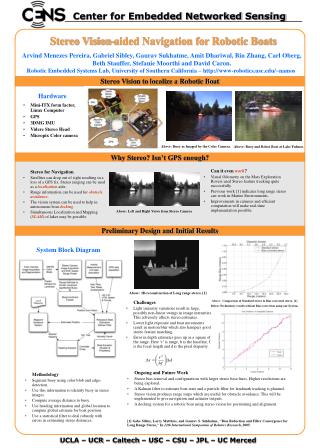
Bin picking Application • In a layered application, a pair of Sony XC-HR70 cameras is mounted orthogonally on a custom gripper for bin picking.
The pre-processing module in this chapter consists of three stages namely: • Image Resizing: experiments are conducted to determine the optimal size with the objective of retaining object shape and features. • Regional Filtering: using filtering techniques to smooth the intensity of the object region • Median Filtering: performs median filtering of the image matrix in two dimensions
Median Filter • Normally use to reduce noise in an image • The current pixel intensity is replaced by the median value of its neighboring pixels. • The median is calculated by first sorting all the pixel values from the surrounding neighborhood into numerical order and then replacing the pixel being considered with the middle pixel value. (If the neighborhood under consideration contains an even number of pixels, the average of the two middle pixel values is used.)
Median Filter • The example show in this figure using 3x3 square neighborhood. • Large neighborhood produce more severe smoothing.
Median Filter Example • Figure shows the original image.
We used 7x7 median filter to eliminate the noise. • the image is beginning to look a bit `blotchy'
Disadvantage of median filter • One of the major problems with the median filter is that it is relatively expensive and complex to compute. To find the median it is necessary to sort all the values in the neighborhood into numerical order and this is relatively slow. • Considered the speed.
Image Restoration • Definition: Filtering procedures aimed at estimating the original image by removing the blurring and noise suppression that occur during image processing. • In many applications (e.g., satellite imaging, medical imaging, astronomical imaging, poor-quality family portraits) the imaging system introduces a slight distortion. Often images are slightly blurred and image restoration aims at deblurring the image.
Binarization • The filtered images obtained from the pre-processing module are gray scale images. In the gray scale image of the bin, the object on the top will not have occlusions and will have the greatest gray value in comparison to the other objects • By applying an appropriate threshold gray value the top object can be separated. To accomplish this, gray scale images are to be converted to binary images by applying a suitable threshold.
Segmentation • One of the harder problems in machine vision is the segmentation of an image into regions corresponding to different objects. • This chapter focuses on analyzing the acquired stereo images of the objects to identify the topmost object inside the bin. Identifying the topmost object can be accomplished by the image segmentation techniques .
Image segmentation refers to the decomposition of an image into its constituent parts or objects. This is a key step in image analysis. Segmentation is one of the most important elements of an automated vision system because only at this stage of image processing the objects are extracted from a scene for subsequent recognition and analysis.
Segmentation algorithms are based on one of the two basic principles: (i) Discontinuity: is based on edge detection. (ii) Similarity: is based on threshold and region growing.
Image segmentation techniques can be broadly classified into six categories namely • Thresholding: can be further categorized into two, gray level thresholding and color thresholding • Clustering: uses data clustering. all feature vectors of an image are assigned to their closest cluster • Boundary-based: segment an image into regions of common attribute by detecting the boundary of each region. Boundary detection can be accomplished by means of edge detection.
Region-based: comprise of region growing techniques, split and merge and watershed segmentations • Template matching Methods • Texture: computes texture coarseness of image pixels to detect changes in coarseness of the texture measure
Thresholding • Definition: Thresholding is used to segment an image by setting all pixels whose intensity values are above a threshold to a foreground value and all the remaining pixels to a background value. • Thresholding often provides an easy and convenient way to perform this segmentation on the basis of the different intensities or colors in the foreground and background regions of an image. • In addition, it is often useful to be able to see what areas of an image consist of pixels whose values lie within a specified range, or band of intensities (or colors). Thresholding can be used for this as well.
Thresholding • The input to a thresholding operation is typically a grayscale or color image. In the simplest implementation, the output is a binary image representing the segmentation. Black pixels correspond to background and white pixels correspond to foreground (or vice versa). • In simple implementations, the segmentation is determined by a single parameter known as the intensity threshold. In a single pass, each pixel in the image is compared with this threshold. If the pixel's intensity is higher than the threshold, the pixel is set to, say, white in the output. If it is less than the threshold, it is set to black.
Segmentation by Thresholding • The simplest method of doing segmentation. • Many objects or image regions are characterized by constant reflectivity or light absorption of their surface. • Thresholding is computationally inexpensive and fast. • Thresholding can easily be done in real time using specialized hardware.