MMU Memory Management Unit Chapter # 14
MMU Memory Management Unit Chapter # 14. Presented by: . Group#13 Asmaa Rabie Abdualaziz Islam Ameen Abdualaziz Doaa Ahmed Mohamed Sherif Mohamed Medhat. Presented to : Dr.Amr Wassal CMP 2012. Agenda. 1. What we will learn from chapter ? 2. Introduction


MMU Memory Management Unit Chapter # 14
E N D
Presentation Transcript
MMU Memory Management Unit Chapter # 14 Memory Management Unit
Presented by: • Group#13 • AsmaaRabieAbdualaziz • Islam AmeenAbdualaziz • Doaa Ahmed Mohamed • Sherif Mohamed Medhat • Presented to: • Dr.AmrWassal • CMP 2012 Memory Management Unit
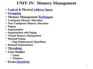
Agenda • 1. What we will learn from chapter ? • 2. Introduction • 3. Moving From An MPU To An MMU • 4. How Virtual Memory works 4.1 The components of a virtual memory system 4.2 Defining Regions Using Pages 4.3 Multitasking and The MMU 4.4Memory Organization in a Virtual Memory System • 5. Details Of The ARM MMU • 6. Page Table 6.1 Level 1 6.2 Translation Table Base Address 6.3 Level 2 • 7. Translation Lookaside Buffer 7.1 L1 Page table virtual-to-physical memory translation using 1 MB sections 7.2 Two-level virtual-to-physical address translation using coarse page tables 7.3 TLB Operations • 8. Domain & Access permission • 9. Caches and Write Buffer • 10.Coprocessor 15 and MMU configuration • 11. Fast Context Switch Extension (FCSE) • 12. A small virtual memory system Memory Management Unit
What will we learn from chapter? Learn basics of ARM MMU and some basic concepts that underlie the use of the virtual memory Memory Management Unit
Agenda • 1. What we will learn from chapter ? • 2. Introduction • 3. Moving From An MPU To An MMU • 4. How Virtual Memory works 4.1 The components of a virtual memory system 4.2 Defining Regions Using Pages 4.3 Multitasking and The MMU 4.4Memory Organization in a Virtual Memory System • 5. Details Of The ARM MMU • 6. Page Table 6.1 Level 1 6.2 Translation Table Base Address 6.3 Level 2 • 7. Translation Lookaside Buffer 7.1 L1 Page table virtual-to-physical memory translation using 1 MB sections 7.2 Two-level virtual-to-physical address translation using coarse page tables 7.3 TLB Operations • 8. Domain & Access permission • 9. Caches and Write Buffer • 10.Coprocessor 15 and MMU configuration • 11. Fast Context Switch Extension (FCSE) • 12. A small virtual memory system Memory Management Unit
Virtual addresses: Assign by Compiler and Linker Introduction • Physical addresses : Access the actual hardware components Memory Management Unit
Agenda • 1. What we will learn from chapter ? • 2. Introduction • 3. Moving From An MPU To An MMU • 4. How Virtual Memory works 4.1 The components of a virtual memory system 4.2 Defining Regions Using Pages 4.3 Multitasking and The MMU 4.4Memory Organization in a Virtual Memory System • 5. Details Of The ARM MMU • 6. Page Table 6.1 Level 1 6.2 Translation Table Base Address 6.3 Level 2 • 7. Translation Lookaside Buffer 7.1 L1 Page table virtual-to-physical memory translation using 1 MB sections 7.2 Two-level virtual-to-physical address translation using coarse page tables 7.3 TLB Operations • 8. Domain & Access permission • 9. Caches and Write Buffer • 10.Coprocessor 15 and MMU configuration • 11. Fast Context Switch Extension (FCSE) • 12. A small virtual memory system Memory Management Unit
Moving From An MPU To An MMU • What is the difference between active and dormant region? • Difference Between MPU & MMU Memory Management Unit
Agenda • 1. What we will learn from chapter ? • 2. Introduction • 3. Moving From An MPU To An MMU • 4. How Virtual Memory works 4.1 The components of a virtual memory system 4.2 Defining Regions Using Pages 4.3 Multitasking and The MMU 4.4Memory Organization in a Virtual Memory System • 5. Details Of The ARM MMU • 6. Page Table 6.1 Level 1 6.2 Translation Table Base Address 6.3 Level 2 • 7. Translation Lookaside Buffer 7.1 L1 Page table virtual-to-physical memory translation using 1 MB sections 7.2 Two-level virtual-to-physical address translation using coarse page tables 7.3 TLB Operations • 8. Domain & Access permission • 9. Caches and Write Buffer • 10.Coprocessor 15 and MMU configuration • 11. Fast Context Switch Extension (FCSE) • 12. A small virtual memory system Memory Management Unit
How Virtual Memory works 0x0400 00e3 00e3 0x0800 Memory Management Unit
The components of a virtual memory system Virtual memory Physical memory MMU Page tables PTE Page frame Relocation register Page Memory Management Unit
Defining Regions Using Pages Virtual Memory Physical Memory Page tables Stack Region 3 RAM Data Region 2 Flash Text Region 1 Page frame Page PTE Memory Management Unit
Multitasking and The MMU Memory Management Unit
Memory Organization in a Virtual Memory System Memory Management Unit
Agenda • 1. What we will learn from chapter ? • 2. Introduction • 3. Moving From An MPU To An MMU • 4. How Virtual Memory works 4.1 The components of a virtual memory system 4.2 Defining Regions Using Pages 4.3 Multitasking and The MMU 4.4Memory Organization in a Virtual Memory System • 5. Details Of The ARM MMU • 6. Page Table 6.1 Level 1 6.2 Translation Table Base Address 6.3 Level 2 • 7. Translation Lookaside Buffer 7.1 L1 Page table virtual-to-physical memory translation using 1 MB sections 7.2 Two-level virtual-to-physical address translation using coarse page tables 7.3 TLB Operations • 8. Domain & Access permission • 9. Caches and Write Buffer • 10.Coprocessor 15 and MMU configuration • 11. Fast Context Switch Extension (FCSE) • 12. A small virtual memory system Memory Management Unit
Details Of The ARM MMU Page tables Translation Lookaside Table (TLB) Domain and access permission Caches and write buffer CP15: c1 control register Fast Context Switch Extension Memory Management Unit
Agenda • 1. What we will learn from chapter ? • 2. Introduction • 3. Moving From An MPU To An MMU • 4. How Virtual Memory works 4.1 The components of a virtual memory system 4.2 Defining Regions Using Pages 4.3 Multitasking and The MMU 4.4Memory Organization in a Virtual Memory System • 5. Details Of The ARM MMU • 6. Page Table 6.1 Level 1 6.2 Translation Table Base Address 6.3 Level 2 • 7. Translation Lookaside Buffer 7.1 L1 Page table virtual-to-physical memory translation using 1 MB sections 7.2 Two-level virtual-to-physical address translation using coarse page tables 7.3 TLB Operations • 8. Domain & Access permission • 9. Caches and Write Buffer • 10.Coprocessor 15 and MMU configuration • 11. Fast Context Switch Extension (FCSE) • 12. A small virtual memory system Memory Management Unit
Page Table L1 Entries for translating 1 MB pages Pointers to the starting address to level 2 page tables L2 Fine page table Coarse page table Memory Management Unit
Level 1 Level 1 page table accepts four types of entry A 1MB section translation entry A directory entry that points to a fine L2 page table A directory entry that points to a coarse L2 page table A fault entry that generates an abort exception Memory Management Unit
Section Entry Access Permission L1 page entries The upper 12 bits of the page table entry replace the upper 12 bits of the virtual address to generate the physical address Domain Cached Buffered Memory Management Unit
Coarse Entry L1 page entries a pointer to the base address of a second-level coarse page table Domain information for the 1 MB section of virtual memory represented by the L1 table entry. Memory Management Unit
Fine Entry L1 page entries Domain information for the 1 MB section of virtual memory represented by the L1 table entry. a pointer to the base address of a second-level fine page table Memory Management Unit
Fault Entry L1 page entries Memory Management Unit
The CP15:c2 register holds the translation table base address (TTB)—an address pointing to the location of the master L1 table in virtual memory. Translation Table Base Address Memory Management Unit
Level 2 Level 2 page table accepts four types of entry A large page entry defines the attributes for a 64 KB page frame. A small page entry defines a 4 KB page frame. A tiny page entry defines a 1 KB page frame. A fault page entry generates a page fault abort exception when accessed. Memory Management Unit
L2 page entries The entry also has four sets of permission bit fields Large page A large PTE includes the base address of a 64 KB block of physical memory. Memory Management Unit
The entry also has four sets of permission bit fields L2 page entries Small page A small PTE holds the base address of a 4 KB block of physical memory Memory Management Unit
L2 page entries The entry also has 1 permission bit fields Small page A tiny PTE provides the base address of a 1 KB block of physical memory. Memory Management Unit
L2 page entries Fault Memory Management Unit
Agenda • 1. What we will learn from chapter ? • 2. Introduction • 3. Moving From An MPU To An MMU • 4. How Virtual Memory works 4.1 The components of a virtual memory system 4.2 Defining Regions Using Pages 4.3 Multitasking and The MMU 4.4Memory Organization in a Virtual Memory System • 5. Details Of The ARM MMU • 6. Page Table 6.1 Level 1 6.2 Translation Table Base Address 6.3 Level 2 • 7. Translation Lookaside Buffer 7.1 L1 Page table virtual-to-physical memory translation using 1 MB sections 7.2 Two-level virtual-to-physical address translation using coarse page tables 7.3 TLB Operations • 8. Domain & Access permission • 9. Caches and Write Buffer • 10.Coprocessor 15 and MMU configuration • 11. Fast Context Switch Extension (FCSE) • 12. A small virtual memory system Memory Management Unit
Translation Lookaside Buffer • Fully associative cache of recently used translations • Stores Access permission set • Use round-robin replacement algorithm • Supports flush and lock operations Memory Management Unit
L1 Page table virtual-to-physical memory translation using 1 MB sections Base offset Virtual address L1 master page table Page table entry Translation table base address Selects physical memory physical address offset Base Copied to TLB Memory Management Unit
Two-level virtual-to-physical address translation using coarse page tables L2 offset Page offset Virtual address L1 offset Step 1 L1 master page table Coarse L2 page table L2 Page table entry Step 2 L1 Page table entry Translation table base address L2 Page table base address Physical Base Page offset physical address Copied to TLB Memory Management Unit
Lock down 42f4 TLB Operations 6726 6726 3889 ab56 35de Flush 9001 9001 f8d9 8845 8787 7842 8fd3 8fd3 9999 Memory Management Unit
Agenda • 1. What we will learn from chapter ? • 2. Introduction • 3. Moving From An MPU To An MMU • 4. How Virtual Memory works 4.1 The components of a virtual memory system 4.2 Defining Regions Using Pages 4.3 Multitasking and The MMU 4.4Memory Organization in a Virtual Memory System • 5. Details Of The ARM MMU • 6. Page Table 6.1 Level 1 6.2 Translation Table Base Address 6.3 Level 2 • 7. Translation Lookaside Buffer 7.1 L1 Page table virtual-to-physical memory translation using 1 MB sections 7.2 Two-level virtual-to-physical address translation using coarse page tables 7.3 TLB Operations • 8. Domain & Access permission • 9. Caches and Write Buffer • 10.Coprocessor 15 and MMU configuration • 11. Fast Context Switch Extension (FCSE) • 12. A small virtual memory system Memory Management Unit
Domain & Access permission • There are two different controls to manage a task’s access permission to memory. • Primary: is the Domain. • Secondary: is access permission set in the page tables. • Domain control basic access to virtual memory by isolating on area of memory from another when sharing common virtual memory map Memory Management Unit
Domain bit access bit assignment Memory Management Unit
Page Table-Based Access permission Memory Management Unit
Agenda • 1. What we will learn from chapter ? • 2. Introduction • 3. Moving From An MPU To An MMU • 4. How Virtual Memory works 4.1 The components of a virtual memory system 4.2 Defining Regions Using Pages 4.3 Multitasking and The MMU 4.4Memory Organization in a Virtual Memory System • 5. Details Of The ARM MMU • 6. Page Table 6.1 Level 1 6.2 Translation Table Base Address 6.3 Level 2 • 7. Translation Lookaside Buffer 7.1 L1 Page table virtual-to-physical memory translation using 1 MB sections 7.2 Two-level virtual-to-physical address translation using coarse page tables 7.3 TLB Operations • 8. Domain & Access permission • 9. Caches and Write Buffer • 10.Coprocessor 15 and MMU configuration • 11. Fast Context Switch Extension (FCSE) • 12. A small virtual memory system Memory Management Unit
Caches and Write Buffer Memory Management Unit
Agenda • 1. What we will learn from chapter ? • 2. Introduction • 3. Moving From An MPU To An MMU • 4. How Virtual Memory works 4.1 The components of a virtual memory system 4.2 Defining Regions Using Pages 4.3 Multitasking and The MMU 4.4Memory Organization in a Virtual Memory System • 5. Details Of The ARM MMU • 6. Page Table 6.1 Level 1 6.2 Translation Table Base Address 6.3 Level 2 • 7. Translation Lookaside Buffer 7.1 L1 Page table virtual-to-physical memory translation using 1 MB sections 7.2 Two-level virtual-to-physical address translation using coarse page tables 7.3 TLB Operations • 8. Domain & Access permission • 9. Caches and Write Buffer • 10.Coprocessor 15 and MMU configuration • 11. Fast Context Switch Extension (FCSE) • 12. A small virtual memory system Memory Management Unit
Coprocessor 15 and MMU configuration Memory Management Unit
Agenda • 1. What we will learn from chapter ? • 2. Introduction • 3. Moving From An MPU To An MMU • 4. How Virtual Memory works 4.1 The components of a virtual memory system 4.2 Defining Regions Using Pages 4.3 Multitasking and The MMU 4.4Memory Organization in a Virtual Memory System • 5. Details Of The ARM MMU • 6. Page Table 6.1 Level 1 6.2 Translation Table Base Address 6.3 Level 2 • 7. Translation Lookaside Buffer 7.1 L1 Page table virtual-to-physical memory translation using 1 MB sections 7.2 Two-level virtual-to-physical address translation using coarse page tables 7.3 TLB Operations • 8. Domain & Access permission • 9. Caches and Write Buffer • 10.Coprocessor 15 and MMU configuration • 11. Fast Context Switch Extension (FCSE) • 12. A small virtual memory system Memory Management Unit
Fast Context Switch Extension (FCSE) • Enables multiple independent tasks to run in a fixed overlapping area of memory • FCSE eliminates the need of flushing the cache and TLB • Uses process ID to convert overlapping virtual address(VA) to a unique modified virtual address(MVA) • MVA = VA + (0x200000 * process ID) Memory Management Unit
Steps to perform context switch when using FCSE Save active tasks context and put the task in dormant state Write the awakening task’s process ID to CP15:c13 Locate set the current tasks' domain to no access and the awakening task’s domain to client access by writing to cp15:c3:c0 Restore the context of awakening task Resume execution of re stored task Memory Management Unit
Agenda • 1. What we will learn from chapter ? • 2. Introduction • 3. Moving From An MPU To An MMU • 4. How Virtual Memory works 4.1 The components of a virtual memory system 4.2 Defining Regions Using Pages 4.3 Multitasking and The MMU 4.4Memory Organization in a Virtual Memory System • 5. Details Of The ARM MMU • 6. Page Table 6.1 Level 1 6.2 Translation Table Base Address 6.3 Level 2 • 7. Translation Lookaside Buffer 7.1 L1 Page table virtual-to-physical memory translation using 1 MB sections 7.2 Two-level virtual-to-physical address translation using coarse page tables 7.3 TLB Operations • 8. Domain & Access permission • 9. Caches and Write Buffer • 10.Coprocessor 15 and MMU configuration • 11. Fast Context Switch Extension (FCSE) • 12. A small virtual memory system Memory Management Unit
A small virtual memory system 3 Tasks The same execution region 256 MB of memory for peripheral devices Very simple example! Memory Management Unit
How to setup the MMU? Define a fixed system software region Define 3 virtual memory maps for the 3 tasks Locate regions in step 1 & 2 into the physical memory Define and locate the page tables within the page table region Data structures for regions and page tables Initialize the MMU, caches, and write buffer Set up a context switch routine to switch between tasks Memory Management Unit
The OS kernel code and data • Fixed addressing to avoid the complexity of remapping when changing to a system mode context. • Shared libraries • The transition routines for switching from privileged mode to user mode during a context switch • 16 KB for the master table • 1 KB each for the four • L2 tables. • 12 KB free memory • Controls the system device I/O space • Noncached & Nonbuffered region 1- Fixed system software region 1MB 32 KB 32 KB 32 KB Memory Management Unit
Text, data, and stack of the running user task. • Remap the Task region on task switch 2- Define Virtual Memory Maps for Each Task • Discussed! 32 KB 32 KB Memory Management Unit