Conveyor Control
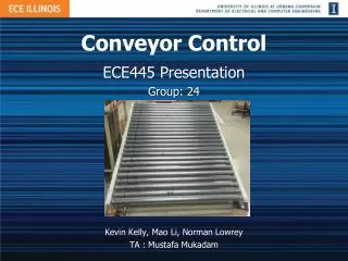
Conveyor Control. ECE445 Presentation Group: 24. Kevin Kelly, Mao Li, Norman Lowrey TA : Mustafa Mukadam. Introduction. Powered conveyor system for Jerry Sanders Robotics Competition Robots complete a task and conveyor changes direction

Conveyor Control
E N D
Presentation Transcript
Conveyor Control ECE445 Presentation Group: 24 Kevin Kelly, Mao Li, Norman Lowrey TA : Mustafa Mukadam
Introduction • Powered conveyor system for Jerry Sanders Robotics Competition • Robots complete a task and conveyor changes direction • Conveyor maintains speed, preventing robots from traversing in wrong direction
Features • Bi-directional • Maintains speed • Adjustable speeds • Dual motors
Circuit Modules 12V/5V Power Supply H Bridge Dead-time Circuit Motor Driver
Overview Power Supply 5V 12V DC Motor To Encoder Encoder MCU Dead-time Logic Motor Driver 60V H Bridge
H-Bridge • Require variable motor speed • Require bi-directional control • H-bridge configuration satisfies these specifications
H-Bridge Configuration • (S3 open, S4 closed) • (S1 open, S2 closed) S3 S3 S1 S1 + Vm - + Vm - + + Vin Vin - - S2 S2 S4 S4 switch action for
H-Bridge Tests • Tested at , resistive (45 Ω) load • Manually operated switch gates with power supplies • Able to achieve +2 V, 0 V, -2 V outputs
H-Bridge Requirements • Must support at least as well as peak drain current • IRF PS40N50L power MOSFETS support 500 V and 46 A • Need to determine proper protection elements to prevent driver damage
Motor Driver • LM5101 Half Bridge Driver • Buffer between control • units and power circuits • Amplifies signals from • control units • Drives H-bridge with • 12V signal • Has some protection • against the noises from H-bridge and motor
Motor Driver Test Results • Module setup. From left to • right: deadtime circuit, motor • driver, H-Bridge • Power to motor • The voltage across the motor • PWM signal duty cycle 75%
PID Algorithm Start • MCU counts rising edges of encoder channel • Speed calculated using set sample time • Output computation: • error = reference speed – actual speed • rpmdiff = last speed – current speed Set Kp, Ki, Kd NO Invert Kp, Ki, Kd Forward? YES Check Speed Calculate Error Update Speed
PID Performance • Working system was responsive • Increased duty cycle when running below reference speed • Decreased duty cycle when running above reference speed • Conveyor exhibited “jerky” motion • Adjustments likely necessary for the PID gains • PWM duty cycle does exceed 90% • No tests were performed under loaded conditions
Dead Time Circuit • Provide input signal to each motor driver • PWM • Complemented PWM • Off (0 V) • On (5 V) • Introduce dead time between PWM transitions
Design Premise high-side output Is “on” safe? Is “on” safe? Q Q MUX MUX D D 0 low-side output 1
Test Results 5 V/vertical division200 µs/horizontal division • High and low-side outputs never simultaneously high • Direction input controls which two flip-flops respond to the input PWM
Features • Dead time controlled by clock frequency • must be longer than slowest switch transition • desire short to maximize full load voltage • Direction controlled by low-voltage signal • satisfies design specification
12V/5V Power Supply • Provides +5V/+12V Vcc and GND to digital Circuit • A maximum current of 1A (only need 115 mA in verifications) • Low noises at load/no load conditions
Power Supply Design • Diodes rectifies AC to DC • Large capacitor smoothes the ripples • LM7812 and LM7805 output 12V/5V with low ripples
Future Work • PC or tablet interface for remote adjustments/control • LCD display for speed • Isolation between driver and H bridge • Problem burning out driver chips • Size considerations • Dead time could be implemented using single chip or microcontroller • Make use of PCBs • No tests were performed under loaded conditions
Video Demonstration • PID seems to be “working” • Notice on-off motion • https://www.youtube.com/watch?v=3om9hObbI3s