Download
1 / 19
190 likes | 402 Vues
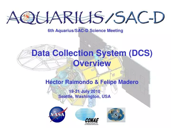
6th Aquarius/SAC-D Science Meeting. Data Collection System (DCS) Overview Héctor Raimondo & Felipe Madero. 19-21 July 2010 Seattle, Washington, USA. DCS Components. Data Collection Platform (DCP) Instrument on board Observatory (DCS/PAD) TT&C Ground Station (CETT)

E N D
6th Aquarius/SAC-D Science Meeting Data Collection System (DCS) Overview Héctor Raimondo & Felipe Madero 19-21 July 2010 Seattle, Washington, USA
DCSComponents • Data Collection Platform (DCP) • Instrument on board Observatory (DCS/PAD) • TT&C Ground Station (CETT) • Pre Processing and Distribution Center (CETT) • Users CETT: Centro Espacial Teófilo Tabanera / Teófilo Tabanera Space Center. (Cordoba – Argentina)
DCS Definitions • DCS (Data Collection System) is a system designed to collect information from ground or near ground user platforms (Data Collection Platform - DCP) by a satellite with a data receiver. • The DCP transmit information asynchronously and this data is decoded and stored onboard the satellite for later transmission to Earth. • The Pre Processing and Distribution Center receives the data from the Observatory, which is processed and addressed to the users.
Main Characteristics Overview • System Argentine DCS • Mission SAC-D (Environmental Data Collection) • Coverage National / Regional • Operational Mode Store and Forward • Routing Falda del Carmen • Proc and Dist Center Falda del Carmen • Platform Density 200 (maximum at Argentine territory) • Platform Operation Random transmission (30 to 220 sec period) • Revisit 2/4 contacts per day • Footprint 2300 Km
Main Characteristics Overview • Message type Argos Compatible • Message Size 46 bytes Maximum useful data 32 bytes • Tx Message duration Max 920 ms • DCP position none (GPS optional) • Reliability CRC (optional) • Uplink UHF 401.55 MHz • Data Security N/A • Platform compatible Argos Compatible • User access delay < 1day • Simultaneous 1 max • message received
Modos de Operación The DCS has 5 operation modes. One of them is related to the data acquisition (environmental parameters). The others 4 operation mode refer to configuration and test. MODE 2 – DCP_RX: In this mode the DCS could collect and store data from land platforms (DCPs).
DCS-FRAMES 5 frame types was defined to the DCP-DCS-PAD system: C-FRAMES, R-FRAMES, DCP-FRAMES, I-FRAMES and T-FRAMES • The land platforms (DCPs) send data frames with information to DCS, then the DCS generates the DCP-FRAMES. • When the DCP Frames are received by DCS, the data is merged with other information generated by DCS, such as: doppler-shift, local time-stamp, AGC value, etc. • This mixture of DCP Frame and DCS Information is calledI-FRAME. • (Mode 2 - DCP_RX I-FRAME )
DCP-FRAMES The data received from land platform will be completely compatible with ARGOS system format. The DCS will save the D to G fields asDCP-FRAME. This frame could have between 7 bytes (N=1, without CRC) and 36 bytes (N=8, with CRC). The CRC (cyclic redundancy check) is set by the platform and it is optional. • “F-Sensor data” field: • 32 sensors could be connected to one DCP Transmitter • Each measure, from one instrument, could use since 1 to 32 bits. • The length of Sensor Data Field could be on range of 32 to 256 bits
TimeStamp • The DCS system stamps a time mark (OBT+OBTfix) on data received from land platforms (DCP) with milliseconds precision but those data could have been acquired long time before to be transmitted by DCP and received by DCS. • The DCP should mark the instrument measures with the hour and the day at least. The rest of date could be calculated from OBT. • Generic schema for the “F-Sensor data” field • N sensor could be installed on each land platform. • Measurements (of de N sensors set) could be separated in period of X hours of time and it could be stored up to Y measurements’ set in one message (message max length: 32 bytes) • It must be fulfilled the next rules: • X period * Y measures = 24 hours • Bytes needed to store N sensors * Y measures <= 30 bytes • The first 2 bytes of F field will be used to specify the day of month and the hour of the last measure period stored on message. The previous message hour will be calculated subtracting the interval or X period.
TimeStamp • Example: • DCP’ sensors : N • Period of measurement (of de N sensors set) : 4 hours • Measurement (of de N sensors set) per day: 6 • Measurements (of de N sensors set) could be included in 5 bytes.
I-FRAMES The I Frames are generated by the DCS joining the DCP-Frame and DCS data at the DCP Frame acquisition moment. Local Data: Doppler-shift, local time-stamp, AGC value, etc. (Engineering Data)
DCS Ground Segment Overview • TT&C Ground Station • Command and manage the on board DCS Instrument • Receive and process the DCS data • Add ancillary data to the data • Send the information to Data Collection Distribution Facilities • Data Collection Pre Processing Distribution Facilities • DCP Data classification and catalog • DCP Data processing (user optional) • Data distribution to user
Products • Raw Data (Level 0) • Numerical values of sensor output (no physical parameter). • it's up to user to convert them to physical values. • Physical Parameter (Level 1) • Correspond to the physical parameter measured by the sensor, for example, air temperature, wind speed, etc. • Physical values calculated by reading a calibration curve or transfer function, to interpret the raw sensor outputs. • Examples of a sensor calibration curve defined with points supplied by user.
Characteristics: • Both product levels (L0-bin and L1-physical) will be stored in the CUSS. • Level0 will be stored as separated files in binary format • All Level1 data will be stored in Relational Database. • Those values will be accessed using query by form. • DB will be prepared with an specifically structure related on project organization. • There will be different access configurations for the different kind of users. • Some data will be published and other will be restricted. This restriction level could be configured following our requirements. • The way of data will be grouped is: • Users: the person who is responsible of the one or more programs • Programs: agreement which links the user with each platform. • Platforms: DCP • Sensor Type • Geographic Location • Time Range
I-FRAMES • Con los campos D, E, F y G, del frame que envía la DCP, el instrumento DCS arma el DCP-FRAME y con el DCP-FRAME + los “Datos Locales” arma el I-FRAME que es lo que se enviará al PAD. Estos I-FRAMES son los que el PAD empaquetara en el CSDP y enviara a tierra. • El campo G – CRC” es el CRC que pone la plataforma de tierra y lo usa el DCS para verificar la integridad de los datos de subida (campos A, B, C, D, E y F). Los frames de subida (provenientes de las DCP) con CRC erróneos serán descartados a bordo directamente por el DCS. • Este CRC es opcional, pero será incluido en el DCP-FRAME tal como llegue desde la Plataforma, es decir tendrá el CRC de todos los campos (A hasta F) o cero (si la DCP no calcula CRC).
CONAE Sience Data Paquet -- Sacar Los I-FRAMES del DCS serán empaquetados, por PAD, en un CSDP según el esquema mostrado en la siguiente figura: Los únicos datos útiles para el procesador son OBT, OBTfix, los datos de Ciencia (I-FRAME) y el Modo (de operación). El resto son datos de ingeniería.