Download
1 / 28
280 likes | 568 Vues
Studies on Next Generation Access Technology using Radio over Free-Space Optic Links. Kamugisha Kazaura 1 , Pham Dat 1 , Alam Shah 1 ,Toshiji Suzuki 1 , Kazuhiko Wakamori 1 , Mitsuji Matsumoto 1 , Takeshi Higashino 2 , Katsutoshi Tsukamoto 2 and Shozo Komaki 2

E N D
Studies on Next Generation Access Technology using Radio over Free-Space Optic Links Kamugisha Kazaura1, Pham Dat1,Alam Shah1,Toshiji Suzuki1, Kazuhiko Wakamori1, Mitsuji Matsumoto1,Takeshi Higashino2, Katsutoshi Tsukamoto2and Shozo Komaki2 1Global Information and Telecommunication Institute (GITI), Waseda University, Saitama, Japan 2Graduate School of Engineering, Osaka University, Osaka, Japankazaura@aoni.waseda.jp 17th September 2008 NGMAST 2008
Contents • Introduction • Overview of FSO/RoFSO systems • Experiment setup • Results and analysis • Summary
Global Suburban Urban In-Building Macro-Cell Home-Cell Micro-Cell Pico-Cell Personal-Cell Introduction Wireless communication systems PAN, WSN … Satellite systems … FSO, Cellular systems, WiMAX …
Full-opticalFSO system Optical fiber communication 100 Gbps FSO communication 10 Gbps Visible light communications MM wave communication 1 Gbps Optical WLAN UWB IrDA PAN Data rate 100 Mbps WiMAX WLANa/b/g 10 Mbps Personal areaCommunication Long distance communication Bluetooth 1 Mbps ZigBee 100 Kbps 1 km 100 km 1 m 10 m 100 m 10 km Communication distance Introduction cont. Wireless communication technologies and standards
Cooperation of fiber comm. Wireless BB environment 1T WDM 100G 100G-Ether 10G SONET(trunk line) 10G-Ether standard FSO 2.5G (Eye safe) FSO10G(WDM) 1G Data rate 1G-Ethernet standard FSO 1G FWA 50M (5GHz) 100M FTTH 1G FWA 46M (26G) FSO 100M Indoor FSO (P-MP) FTTH 10M FWA 10M (22&26G) 11g Indoor FSO(P-MP) 11a Radio on FSO FSO 10M 12M 24M 8M 1M IEEE802.11b ADSL 1.5M FWA 1.5M (22&26G) 100K CATV,cellular phone Video use Analog FSO system ISDN ~1995 ~2000 2001 2002 2003 2004 2005 ~2010 Introduction cont. FSO roadmap
Visible light Cosmic radiation T radiation V radiation IR radiation Communications radiation X ray radiation Microwave, radar TV VHF SW Frequency (Hz) 1020 1018 1016 1014 1012 1010 108 106 250 THz (1 THz) (1 GHz) (1 MHz) (1 pm) (1 nm) (1 μm) (1 mm) (1 m) (100 m) Wavelength (m) 10-12 10-9 10-6 10-3 100 102 λ = wavelengthf = frequency C0 = 300 000 km/sC = λ x f Visible light Fiber transmissionwavelength range 0.4 0.5 0.6 0.7 0.8 0.9 1.0 1.1 1.2 1.3 1.4 1.5 1.6 μm 670 780 850 1300 1550 1625 nm Overview of FSO/RoFSO systems FSO is the transmission of modulated visible or infrared (IR) beams through the atmosphere to obtain broadband communications.RoFSO contains optical carriers modulated in an analogue manner by RF sub-carriers. Merits • Secure wireless system not easy to intercept • Easy to deploy, avoid huge costs involved in laying cables • License free • Possible for communication up to several kms • Can transmit high data rate De merits • High dependence on weather condition (rain, snow, fog, dust particles etc) • Can not propagate through obstacles • Susceptible to atmospheric effects (atmospheric fluctuations) Electromagnetic spectrum
Internet Mountainous terrain Metro network extension RoFSO transceiver and remote BS Backhaul(~5 km) Areas with nofiber connectivity RoFSO link Optical fiber link RF based links RoFSO transceiver Remote locatedsettlements Data relay satellite Inter-satellite link Space station High-speed (10Gbs) optical feeder link Demonstration of 2.5 Gbps link Ground stationwith adaptive optics Fiber optic link FSO technology application scenarios Overview of FSO/RoFSO systems cont. Terrestrial • Metro network extension • Last mile access • Enterprise connectivity • Fiber backup • Transmission of heterogeneous wireless services Space • Inter-satellite communication (cross link) • Satellite to ground data transmission (down link) • Deep space communication
FSO antenna Optical source module Optical fiber FSO channel Electrical signal O/E and E/Oconversion module Direct coupling of free-space beam to optical fiber FSOantenna Optical fiber WDM FSO channel (b) New full-optical FSO system Overview of FSO/RoFSO systems cont. Conventional FSO system • Operate near the 800nm wavelength band • Uses O/E & E/O conversion • Data rates up to 2.5 Gbps • Bandwidth and power limitations Next generation FSO system • Uses 1550nm wavelength • Seamless connection of space and optical fiber. • Multi gigabit per second data rates (using optical fiber technology) • Compatibility with existing fiber infrastructure • Protocol and data rate independent (a) Conventional FSO system
Cellular DVB WiFi WiMAX Overview of FSO/RoFSO systems cont. Free-space beam directly coupled to optical fiber RoFSO antenna RoF RoF DWDM RoFSOchannel Heterogeneous wireless service signals (c) Advanced DWDM RoFSO system Advanced DWDM RoFSO system • Uses 1550nm wavelength • Transport multiple RF signals using DWDM FSO channels • Realize heterogeneous wireless services e.g. WLAN, Cellular, terrestrial digital TV broadcasting etc
Beam divergence, θ FSO antenna FSO antenna Transmitter Receiver Transmitter Receiver wide beam narrow beam Challenges in design of FSO systems Overview of FSO/RoFSO systems cont. Wide beam FSO systems • Beam divergence in terms of several milliradians • Easy to align and maintain tracking • Less power at the receiver (the wider the beam the less power) Narrow beam FSO systems • Beam divergence in terms of several tens of microradians • Difficult to align and maintain tracking • More optical power delivered at the receiver The narrow transmission of FSO beam of makes alignment of FSO communication terminals difficult than wider RF systems.
Overview of FSO/RoFSO systems cont. FSO system performance related parameters Optical powerWavelengthTransmission bandwidthDivergence angleOptical lossesBERReceive lens diameter & FOV Internal parameters(design of FSO system) FSO Performance VisibilityAtmospheric attenuationScintillationDeployment distancePointing loss External parameters(non-system specific parameters)
Clear day Visibility > 20km Attenuation: 0.06 ~ 0.19 db/km Cloudy day Visibility: ~ 5.36 km Attenuation: 2.58 db/km Rain event Visibility: ~ 1.09 km Attenuation: 12.65 db/km Overview of FSO/RoFSO systems cont. Factors influencing performance of FSO systems Visibility under different weather conditions Visibility greatly influences the performance of FSO systems e.g. fog, rain, snow etc significantly decrease visibility
Transmit power Received power Beam wander Time Time Time Time Scintillation Combined effect Time Overview of FSO systems cont. Factors influencing performance of FSO systems Atmospheric effects Atmospheric turbulence has a significant impact on the quality of the free-space optical beam propagating through the atmosphere. Other effects include: - beam broadening and- angle-of-arrival fluctuations Suppression techniques: - Aperture averaging- Adaptive optics- Diversity techniques- Coding techniques Reduces the optical beam power at the receiver point and causes burst errors
Experimental field Bldg. 14 Waseda University Nishi Waseda Campus 1 km Bldg. 55 Waseda University Okubo Campus Satellite view of the test area Source: Google earth
New RoFSO system experiment setup cont. RoFSO antenna installed on Bldg 14 rooftop Okubo campus Bldg. 55S Beacon signal IR viewer Waseda campus Bldg 14 rooftop
Main transmit and receive aperture Si PIN QPD for coarse tracking using beacon signal BS1 Main transmit and receive aperture Digital mobile radio transmitter tester(Anritsu MS8609A) Post EDFA SMF BS2 collimator FPM(Fine Pointing Mirror) RoFSO antenna tracking adjustment and monitoring PC Beacon signaltransmit aperture InGaAs PIN QPDfor fine tracking Beacon Source Rough tracking beacon projection aperture Opticalsource BoostEDFA DWDM D-MUX Bldg. 14 Nishi Waseda campus Weather measurement device RF-FSO antenna Optical power meter(Agilent 8163A) Atmospheric turbulence effects recording PC Bit Error Rate Tester(Advantest D3371) Atmospheric effects measurement antenna RoFSO antenna Bldg. 55S Okubo campus
New RoFSO system experiment setup diagram RF-FSOantenna RF-FSOantenna RF-FSO link RoFSO link RoFSOantenna RoFSOantenna Opt.circulator Opt.circulator filter EDFA Filter & ATTN TrackingPC Signal Analyzer 2.5Gbps Opt. Tx Power meter 2.5Gbps Opt. Rx Opt. Source Clock Data PC Signal Generator BERT BERT PC Bldg. 14 Nishi Waseda Campus Bldg. 55S Okubo Campus
New RoFSO system experiment Characteristics of FSO antennas used in the experiment
Results: CNR and ACLR characteristics for RF-FSO cont. Effects of weather condition Relationship between CNR and ACLR WCDMA received signal spectrum WCDMA: Wideband Code Division Multiple AccessCNR: Carrier to Noise RatioACLR: Adjacent Channel Leakage Ratio (a quality metric parameter for WCDMA signal transmission)
Results: CNR and ACLR characteristics for RF-FSO 112 dB 45 dB RF signal transmission characteristics measured using RF-FSO system
Results: BER and received power characteristics RoFSO system BER and received power characteristics measured using RoFSO system
Results: CNR characteristics RF-FSO system CNR characteristics measured using RF-FSOsystem
Results: ACLR and optical received power measurement RoFSO system With EDFA: -24.5 dBm Without EDFA: -15 dBm Received 3GPP W-CDMA signal ACLR spectrum(3GPP Test Signal 1 64 DPCH) Variation of ACLR with the measured received optical power
Results: EVM measurement RoFSO system Error Vector Magnitude (EVM) • EVM is the ratio in percent of the difference between the reference waveform and the measured waveform. • EVM metric is used to measure the modulation quality of the transmitter. • The 3GPP standard requires the EVM not to exceed 17.5%
Summary • Presented characteristics of RF signals transmission using FSO links under various weather conditions reflecting actual deployment scenarios. • Measured, characterized and quantified important quality metric parameters e.g. CNR, ACLR, EVM, BER, optical received power etc significant for evaluation of RF signal transmission using FSO links. • A properly engineered RoFSO link can be used as a reliable next generation access technology for providing heterogeneous wireless services in the absence of severe weather conditions. • Further work on simultaneous transmission of multiple RF signals by DWDM technology using the RoFSO system are ongoing. • The results are significant in design optimization, evaluation, prediction and comparison of performance as well as implementation issues/guidelines of RoFSO systems in operational environment.
Supported by This work is supported by a grant from the National Institute of Information and Communication (NICT) of Japan Thank you for your attention Kamugisha KAZAURA (カムギシャ カザウラ) kazaura@aoni.waseda.jp
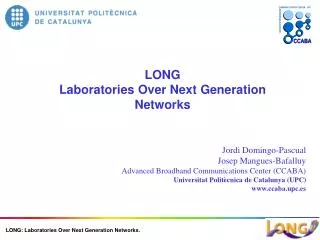
I. Development of an Advanced DWDM RoFSO Link System - Transparent and broadband connection between free-space and optical fiber - DWDM technologies for multiplexing of various wireless communications and broadcasting services DWDM RoF DWDM RoFSO Cellular Mobile NW Cellular BS Scintillation Digital TV FSO Tx,Rx FSO Tx,Rx Digital TV WDM OE, EO WDM WLAN WLAN AP River, Road, etc Internet New Wireless Universal Remote BS New Wireless Services Optical Free-Space Fiber-rich Area Rural Area without Broadband Fiber infrastructure OE/EO OE III. Long-term Demonstrative Measurements - Pragmatic examination of advanced RoFSO link system - Investigation of scintillation influence on various types of wireless services transported using the RoFSO system. II. Development of Seamless Connecting Equipments between RoF, RoFSO and Wireless Systems - Wireless service zone design - Total link design through RoF, RoFSO, and Radio Links OE/EO OE/EO Overview of DWDM RoFSO Link research
Overview of FSO systems cont. Atmospheric effects suppression techniques • Aperture averaging • Reducing scintillation effects by increasing the telescope collecting area. • Adaptive optics • Measure wavefront errors continuously and correct them automatically. • Diversity techniques • Spatial diversity (multiple transmitters and/or receivers) • Temporal diversity (signal transmitted twice separated by a time delay) • Wavelength diversity (transmitting data at least two distinct wavelengths) • Coding techniques • Coding schemes used in RF and wired communications systems.