COMMUNICATION SYSTEM EEEB453 Chapter 6 DIGITAL MODULATION
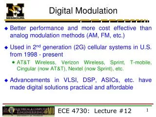
COMMUNICATION SYSTEM EEEB453 Chapter 6 DIGITAL MODULATION. Intan Shafinaz Mustafa Dept of Electrical Engineering Universiti Tenaga Nasional http://metalab.uniten.edu.my/~shafinaz. Digital-to-Analog Conversion. Modulating a digital signal


COMMUNICATION SYSTEM EEEB453 Chapter 6 DIGITAL MODULATION
E N D
Presentation Transcript
COMMUNICATION SYSTEM EEEB453Chapter 6DIGITAL MODULATION Intan Shafinaz Mustafa Dept of Electrical Engineering Universiti Tenaga Nasional http://metalab.uniten.edu.my/~shafinaz
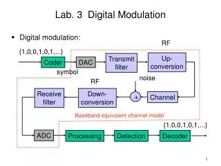
Digital-to-Analog Conversion • Modulating a digital signal • Eg. Sending computer data through public telephone line
B Mbps B MHz Digital-to-Analog Conversion • Process of changing one of the characteristics of an analog signal based on the information in digital signals (0’s and 1’s). • Modulation involved switching (known as keying) between short bursts of different signals to transmit the encoded message. • A general carrier wave may be written: • Modulation methods based on varying the amplitude, A, frequency, f and phase, to transmit digital data is known as Amplitude Shift Keying (ASK), Frequency Shift Keying (FSK) and Phase Shift Keying (PSK) respectively. • Example – Tx of digital data over telephone wire (modem)
Information Capacity, Bits, Bit Rate, Baud and M-ary Encoding. • Information Capacity – is a measure of how much information can be propagated through a communications system and is a function of BW and Tx line. • It represents the number of independent symbols that can be carried through a system in a given unit of time. • Hartley’s law is I B x t Where I = information capacity (bps) B = bandwidth (hertz) t = transmission time (sec)
M-ary Encoding • M-ary is a term derived from the word binary. • M simply represents a digit that corresponds to the number of condition, levels or combinations possible for a given number of binary variables. • For example, a digital signal with four possible conditions is an M-ary system where M = 4. • The number of bits necessary to produce a given number of condition is expressed mathematically as N = log 2M Where N = number of bits necessary M = Number of conditions, levels or combination possible with N bits • Rearranged the equation to express the number of conditions possible with N bits as 2N = M Example, with one bit, only 21 = 2 conditions are possible, with two bits, 22 = 4 conditions are possible etc..
Bit Rate, Baud Rate and Minimum BW • Two basic aspects of digital-to-analog modulation; bit and baud rate. • Bit rate - number of bits per second (rate at which bit changes, bps). • Computer Efficiency – how long it takes to process each piece of information (time to send) • Baud rate – number of signal units per second (rate at which signal element changes). Also called modulation rate or symbol rate. • Data Transmission Efficiency – how efficient we can move those data from place to place. • Analogy – In transportation, baud ≈ car and bit ≈ passenger • A car can carry one or more passengers. If 1000 cars go from one point to another, carrying only 1 passenger (i.e the driver), then 1000 passengers are transported. • However, if each car carries four passengers (carpooling), then 4000 passengers are transported. • Note that the number of cars not the number of passengers, determine the traffic, and therefore, the need for wider highways. • Similarly, the number of bauds determines the required bandwidth, not the number of bits.
Bit Rate, Baud Rate and Minimum BW • According to H. Nyquist, binary digital signals can be propagated through an ideal noiseless transmission medium at a rate equal to two times the bandwidth of the medium. • The minimum theoretical bandwidth necessary to propagate a signal is called the minimum Nyquist bandwith or the minimum Nyquist frequency. • Thus, fb = 2B Where fb = bit rate (bps) B = ideal Nyquist bandwidth (hertz) • Mathematically, Baud = (baud per second) where ts = time of one signaling element (second) N = number of bits per signal element fb = bit rate (bps) In analog Tx of digital data, the baud rate is less than or equal to the bit rate. - In binary system such as binary FSK and binary PSK, baud and bits per second are equal. However, in higher-level system such as QPSK and 8-PSK, bps is always greater than baud.
Bit Rate, Baud rate and Minimum BW Summary of the Terms: 8
Amplitude Shift Keying (ASK) or On-Off Keying (OOK) • A simple version of amplitude modulation used for digital modulation. • Both freq and phase remain constant while the amplitude changes. • Uses logic levels in the data to control the amplitude of the carrier wave. ‘1’ for high amplitude (switch ON) ‘0’ for low amplitude (switch OFF).
Amplitude Shift Keying (ASK) or On-Off Keying (OOK) Basic implementation of Binary ASK
Amplitude Shift Keying (ASK) or On-Off Keying (OOK) • ASK Modulator • - The modulator cct has 2 inputs: 1. data to be transmitted 2. high freq carrier sinewave At the Tx, let the input of a data stream is 0110001011
Amplitude Shift Keying (ASK) or On-Off Keying (OOK) • At the Rx, the data stream need to extracted: Step 1 – Rectify the input ASK waveform to contain only +ve signal but it will still contain unwanted carrier wave component. Step 2 – Pass through a LPF to remove the carrier component. Step 3 – Pass through a voltage comparator to get a true copy of the original data stream
Amplitude Shift Keying (ASK) Example 3 – Determine the baud and minimum bandwidth necessary to pass a 10 kbps binary signal using amplitude shift keying. Solution For ASK, N=1 Bmin = fb/N Bmin = 10k/1 = 10kHz Baud =fb/N = 10kbaud/sec 15
Amplitude Shift Keying (ASK) Example 4 – Given a bandwidth of 5000 Hz for an ASK signal, what are the baud rate and bit rate? Solution In ASK the baud rate is the same as the bandwidth, which means the baud rate is 5000. The baud rate and the bit rate are also the same for ASK, the bit rate is 5000bps. 16
Frequency Shift Keying (FSK) • Use logic levels in the data to control the frequency of the carrier wave. • Data = ‘1’ for high frequency • Data = ‘0’ for low frequency
FSK Bit Rate, Baud and Bandwidth • It can be seen that the time of one bit (tb) is the same as the time the FSK output is a mark or a space frequency (ts). • Thus the bit time equals the time of an FSK signaling element and the bit rate equals the baud. • The baud for binary FSK can also be determined by substituting N = 1, baud =
FSK Bit Rate, Baud and Bandwidth The minimum bandwidth for FSK is given as And since Then the minimum bandwidth can be approximated as (**) Where B = minimum Nyquist bandwidth (hertz) f = frequency deviation (|fm - fs|) (hertz) fb= input bit rate (bps) Note that equation (**) resembles Carson’s rule for determining the approximate bandwidth for an FM wave. The only difference in the two equations is that, for FSK, the bit rate, fbis substituted for the modulation signal freq fm.
FSK Bit Rate, Baud and Bandwidth Example 5 – A binary FSK with a mark frequency of 49kHz, a space frequency of 51kHz and an input bit rate of 2kbps, determine The peak frequency deviation The minimum bandwidth Baud • Solution • From 2f = |fm - fs|, • andf = |49kHz – 51kHz|/2 = 1kHz • b. Min BW, B = 2(f + fb) = 2(1000+2000) = 6kHz • c. For FSK, N = 1, the baud is fb/N =2000/1 = 2000 20
FSK Bit Rate, Baud and Bandwidth Bessel function can also be used to determine the approximate bandwidth for an FSK wave. The fastest rate of change i.e highest fundamental freq occurs when alternating 1s and 0s are occuring. Therefore, Where fa = highest fund freq (hz) fb = input bit rate (bps) The formula used for modulation index in FM is also valid for FSK, thus (unitless) Where h = FM modulation index called h-factor in FSK f = peak freq deviation (Hz)
FSK Bit Rate, Baud and Bandwidth The worst-case modulation index (deviation ratio) yields the widest BW. The widest BW occurs when both the freq deviation and the modulating signal freq are at their maximum values, thus or Thus, bandwidth, B = 2(n x fa)
FSK Bit Rate, Baud and Bandwidth Example 6 – A binary FSK with a mark frequency of 49kHz, a space frequency of 51kHz and an input bit rate of 2kbps, using Bessel table, determine The modulation index, h The bandwidth Solution a. h = |49kHz – 51kHz|/2kbps = 1 b. From a Bessel table, for modulation index of 1, n = 3, then B = 2(3 x 1000) = 6kHz 23
Frequency Shift Keying (FSK) • There are many different ways of generating an FSK waveform. • One way is by combining 2 different ASK waveform/modulator.
Frequency Shift Keying (FSK) • Lets assume that the above data stream is applied to an ASK modulator using the higher freq as the carrier. The resulting output: • Inverting the original data stream:
Frequency Shift Keying (FSK) • This inverted data stream will be the input to another ASK modulator using a lower carrier freq - the original data 0 periods filled with a lower freq carrier.
Frequency Shift Keying (FSK) • Summing amplifier is used to add the two ASK waveforms: Output from Modulator 1 Output from Modulator 2
Frequency Shift Keying (FSK) • Advantage of FSK over ASK – higher reliability in term of data accuracy. • Disadvantage – requires higher BW (the actual increase depends on the 2 freqs used). The higher the freq and the more they differ from each other, the wider the BW required.
Multiple FSK (MFSK) A signal that is more bandwidth efficient, but also more susceptible to errors is multiple FSK (MFSK), in which more than two frequencies are used. (i.e each signaling element represents more than one bit) The transmitted MFSK signal for one signal element time can be defined as follows: Where fc= the carrier frequency ∆f = the difference frequency M = number of signal element (2n) n = number of bits per signal element
Example 7– With fc = 350kHz, ∆f = 20kHz, and M=8 (n=3), the following frequency assignments for each of the eight possible 3-bit data combinations:
Example – Figure shows an example of MFSK with M = 4. An input bit streams of 20 bits is encoded 2 bits at a time, with each of the four possible 2-bit combinations transmitted as a different frequency. The display in the figure shows the frequency transmitted (y-axis) as a function of time (x-axis). Each column represents a time Ts in which a single 2-bit signal element is transmitted. The shaded rectangle in the column indicates the frequency transmitted during that time unit.
Phase Shift Keying (PSK) • In PSK, the phase of the carrier is shifted to represent data. • Two-Level PSK(Binary PSK) - BPSK • Uses two phases (0 and 180°) to represent the two binary digits. • The resulting transmitted signal for one bit time is:
Phase Shift Keying (PSK) • Example: binary 1 is represent with a phase 0°, while binary 0 is represented with a phase of 180°. • PSK is equivalent to multiplying the carrier by +1 when the info is 1, and by -1 when the info is 0. Bipolar NRZ binary ‘1’ binary ‘0’
Phase Shift Keying (PSK) • PSK Transmitter – same modulator as in ASK system • Since a sinewave is symmetrical, it is impossible for the Rx to know whether signal is inverted form or not. • Thus need to apply some data conditioning to the incoming stream to convert it to a form which recognizes logic levels by changes that occur and not by the absolute levels. • One such code is bipolar NRZ. • The amplitude of the carrier is controlled by the bipolar signal on the modulation input. When the signal goes negative, the sinewave inverts.
PSK Bit Rate, Baud and Bandwidth • Mathematically, the output of a BPSK modulator is proportional to • Solving for the trig identity for the product of two sine function, • Thus, the minimum double-side Nyquist BW, B is • But , then
PSK Bit Rate, Baud and Bandwidth Example 8 – For a BPSK modulator with a carrier frequency of 70 MHz and an input bit rate of 10Mbps, determine the maximum and minimum upper and lower side frequencies Draw the output spectrum Determine the minimum bandwidth Calculate the baud. 37
Solution a. b. Output spectrum c. d.
The term “quadrature” implies that there are four possible phases (4-PSK) which the carrier can have at a given time. The pair of bits represented by each phase is called dibit. The rate of change (baud) in this signal determines the signal bandwidth. BUT the throughput or bit rate for QPSK is twice the baud rate. Quadrature PSK (QPSK)
QPSK = 4-PSK Assumption 41
Modulation for Data Communication: QPSK • One way to increase the binary data rate while not increasing the bandwidth required for the signal transmission is to encode more than 1 bit per phase change. • In the system known as quadrature, quarternary, or quadra phase PSK (QPSK or 4-PSK), more bits per baud are encoded, the bit rate of data transfer can be higher than the baud rate, yet the signal will not take up additional bandwidth. • In QPSK, each pair of successive digital bits in the transmitted word is assigned a particular phase. • Each pair of serial bits, called a dibit, is represented by a specific phase.
Quadrature PSK modulation. (a) Phase angle of carrier for different pairs of bits. (b) Phasor representation of carrier sine wave. (c) Constellation diagram of QPSK.
QPSK Bit Rate, Baud and Bandwidth Example 9 – The CCITT V.22 (like Bell 212A) modem uses QPSK to send data at 1200 bits per second; What is the baud rate. The CCITT V.22 (like Bell 212A) modem uses QPSK to send data at 1200 bits per second; however, the phases change only 600 times per second, conveying two bits per change - this is a 600 baud modem. 44
QPSK Bit Rate, Baud and Bandwidth Example 10 – For a QPSK system, with the following input bit sequence 100010101101, an input bit rate equal to 20Mbps, Draw the QPSK modulated waveform, state assumption used. Determine the minimum bandwidth required. 45
QPSK Bit Rate, Baud and Bandwidth Solution eg. 9 – 100010101101 Assumption: a. • B = fb/N • B = 20M/2 = 10MHz. 46
QUADRATURE AMPLITUDE MODULATION -Uses both amplitude and phase modulation of the carrier; not only are different phase shifts produced but also the amplitude of the carrier is varied 8 – QAM Is an M–ary encoding technique where M=8
8-QAM Figure : 8-QAM Modulator a) Truth Table b)phasor diagram c) Constellation diagram
8-QAM Figure : Output phase and amplitude versus-time realtionship for 8-QAM Min. bandwidth required = fb/3
Quadrature Amplitude Modulation A combination of ASK and PSK: both phase and amplitude varied #amplitude shifts << #phase shifts Lower susceptible to noise than ASK, higher bit rate than PSK