Download

1 / 61
610 likes | 732 Vues
OSI Model and Standards ITNW 1325, Chapter II. Understanding the OSI Model. Understanding the OSI Model. Overview : Open Systems Interconnection (OSI) – a layered reference model comprised of seven functional layers

E N D
OSI Model and Standards ITNW 1325, Chapter II
Understanding the OSI Model Overview: • Open Systems Interconnection (OSI) – a layered reference model comprised of seven functional layers • Developed by the International Organization for Standardization (ISO) in 1984 – based on their analysis of TCP/IP, IBM SNA, and DECNET protocols • Governed by the ISO Standard 7498 – some vendors build their products according to it (Novell) • Ensures compatibility and solves communication issues among different implementations of network hardware and software
Understanding the OSI Model Overview (continued): • Uses the divide-and-conquer approach to networking from low-level hardware to the high-level software • Constructs a series of independent but interconnected layers – breaks the big problem of communications into smaller problems that are isolated from each other • Individual layers encapsulate specific independent functions – changes to one layer don’t affect other ones • Implements the “peer communication” principle – only identical remote layers communicate to each other
Understanding the OSI Model Overview (continued): • “Universal” resembles “imperfect” – some network functions operate at several layers, while some do not require services from every layer • Practical usage is questioned by many because of its complexity and lack of flexibility The OSI networking model remains a great tool for learning networks – protocols, devices security, and other models
Understanding the OSI Model Reasons for Layering: • Divides communications into a finite number of logical blocks – simplifies comprehension and use • Provides design modularity – allows upgrades to a specific layer to remain separate from the other ones • Allows programmers to specialize in a particular layer of the networking model, with open set of specifications • Encourages interoperability by promoting balance between different networking models • Allows vendors to produce standardized interfaces
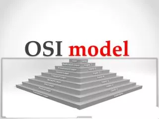
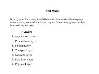
Understanding the OSI Model Seven Layers:
Understanding the OSI Model Peer Communication, Overview: • Each layer is unaware of the activities of all other ones on the same host – doesn’t acknowledge their services • Each layer only communicates logically to an identicallayer on the other side of the communication process – information is passed via headers and trailers added • Headers and trailers added at the sending layer will be read and removed at the peer layer on the other side • Protocol suites combine protocols defined at different layers together to enable network communications
Understanding the OSI Model Peer Communication, Illustration:
Understanding the OSI Model Peer Communication, Advantages: • Allows convenient distribution of networking functions • Permits independent error checking on different layers • Simplifies creation of protocols Peer Communication, Disadvantages: • Results in overhead that grows as data traverses the model from the Application to the Data Link layer • Leads to reduced efficiency of network utilization
OSI Layer Functions Application (L7): • Defines network services that software applications (browsers, e-mail clients, etc) can request from the network and requests the services on their behalf • Accepts data from applications and interprets their formatting and procedures to the network • Interprets data coming from the network and passes it to proper applications • Facilitates multiple important protocols – HTTP, FTP, DNS, Telnet, SMTP, SNMP, etc.
OSI Layer Functions Presentation (L6): • Receives data from the Application layer and prepares it for transmission over the network • Reformats the incoming data from lower layers for specific machine/application combination • Performs encryption and compression of data for outbound communications – as well as decryption and decompression of data for inbound communications • The only layer that restructures data – other ones add headers and/or trailers without reconfiguring the data
OSI Layer Functions Presentation (continued): • Distinguishes between file extensions and coding schemes – BMP, JPG, WAV, MP3, ASCII, HTML, etc. • Example – Presentation layer protocols encode online music tracks into MP3 format • Example – Presentation layer protocols interpret JPG images so that HTTP is able to understand them • Example – Presentation layer protocols encode text using ASCII and other schemes • Example – Presentation layer protocols encode/decode sensitive data within secure Internet connections
OSI Layer Functions Session (L5): • Allows senders and receivers to establish and manage data transmission session – independently of the actual data flow over the network • Detects if the transmission has been cut off, notifies the client software, and restart its at the appropriate point • Determines the order of communication, maximum duration of transmission, and provides clocking or timing for the session • Assists large data transfers – informs the receiver about the beginning/end of the stream that’s broken in pieces
OSI Layer Functions Session (continued): • Allows information of different streams – that may be originating from different sources – to be properly combined or synchronized • Facilitates NetBIOS, SQL, RPC, and other protocols
OSI Layer Functions Transport (L4): • Accepts data from the Session layer services and provides messaging service for them • Facilitates connection-oriented (guarantee of delivery) and connectionless (delivery not guaranteed) protocols • Connection-oriented protocols ensure data delivery – used for sensitive data transmissions over the Internet • Connectionless protocols don’t ensure data delivery – but impose much lower overhead onto the network • Submits data with its header added to the Network layer for further handling
OSI Layer Functions Transport, Connection-Oriented Protocols: • Explicitly establish a session (“connection”) before allowing data to be sent • Ensure data delivery by requiring and acknowledgement (ACK) of the receipt of data packets – retransmit in case an ACK is not timely returned • Negotiate for the highest number of data segments to be sent before an acknowledgement is required • Provide data integrity via checksums – unique character strings attached to data that allow the receiving node to determine if a data unit was modified during delivery
OSI Layer Functions Transport, Connection-Oriented Protocols (continued):
OSI Layer Functions Transport, Connection-Oriented Protocols (continued): • Ensure reliable data delivery by breaking large data units into multiple smaller segments (segmentation) – with segment size related to the MTU size • The MTU size is the maximum data size that nodes on the way can place into their memory buffers • Identify segments that belong to the same message, determine the order of segments (sequencing), and reconstruct the segmented units (reassembly) • Gauge appropriate rate of transmission based on how fast the recipient can accept data (flow control)
OSI Layer Functions Transport, Connectionless Protocols: • Do not establish a connection before sending data • Do not require acknowledgements for data sent – don’t ensure the that the data was properly received • Define a special term for data carried – datagrams • Do not perform error check • Much less sophisticated and have less transmission and processing overhead than connection-oriented ones • Used in cases when data needs to be sent quickly • Example – streaming video and audio transmissions over the network
OSI Layer Functions Transport, Protocols:
OSI Layer Functions Network (L3): • Accepts data from the Transport layer – wraps segments into packets that carry addressing information • May brake large packets into smaller ones – according to capacity of the network (fragmentation) • Defines protocol-dependent logical addressing schemes that uniquely identify nodes within interconnected networks and enable network segmentation • Establishes the best delivery path (routing) considering addressing, delivery priorities, network congestion, quality of service, and cost of the paths (routes)
OSI Layer Functions Network (continued): • Implements congestion control by sensing delays associated with routes and managing how much traffic is sent across them – helpful within busy networks • Internet Protocol (IP) is the most common L3 protocol
OSI Layer Functions Data Link (L2): • Encapsulates packets received from the Network layer into frames – complete packages to be transmitted • Defines the format of the header and/or trailer added to packets received – depend on the network type in use • Common network types are Ethernet and Token Ring – use different frames and can not be used together • Frame format and maximum size map onto the carrying capacity of the network medium • Performs verification of data integrity using checksum mechanism – to detect transmission errors
OSI Layer Functions Data Link (continued): • Implies error correction upon the receiver’s request for retransmission in case a frame is dropped or altered • Manages point-to-point transmission across the medium within the same logical or physical cable segment • Splits into two sublayers with separate duties – Logical Link Control (LLC) and Media Access Control (MAC)
OSI Layer Functions Data Link, Sublayers:
OSI Layer Functions Data Link, Sublayers, LLC: • Interfaces the Network layer – implies intelligence • Packages data frames differently for different networks • Manages flow control and issues requests for retransmission for data with errors Data Link, Sublayers, MAC: • Defines a unique physical identifier – MAC address – for network cards (every frame carries a destination and source MAC addresses) • Defines and manages the access to the physical medium
OSI Layer Functions Data Link, MAC Addresses: • 48-bit non-replaceable, “burned-in” addresses (BIA) - represented using twelve hexadecimal characters • Consist of two parts – a block ID and a device ID • A block ID (“Organizational Unit Identifier, OUI”) – a six-character (24-bit) sequence that uniquely identifies each vendor (managed by IEEE), with large vendors assigned several different block IDs • A device ID (“serial number”) – a six-character (24-bit) sequence that uniquely identifies the device (managed by the manufacturer)
OSI Layer Functions Data Link, MAC Addresses (continued):
OSI Layer Functions Data Link, Frame Integrity: • Before a frame is sent, the sender performs a cyclic redundancy check (CRC) on all of its fields – generates a unique 4-byte frame check sequence (FCS) code • The FCS code is attached to the frame being sent – to be detached and regenerated by receiver • The generated code is compared to the one received – no error is assumed in case the two codes match and a retransmission request is issued in case of mismatch
OSI Layer Functions Data Link, Frame Handling: • All NICs connected to the same physical segment of the network receive and process frames sent • Only NIC with matching destination MAC address passes the payload to the Network layer – other nodes would drop the frame • Broadcast frames are sent to and processed by all nodes on the physical segment – costs performance • Reducing the number of nodes on a physical network – segmentation– improves performance by reducing the number of frames sent and processed
OSI Layer Functions Physical (L1): • Accepts frames from the Data Link layer and turns frame bits into the medium pulses on the sending end • Transforms pulses to bits and passes them to the Data Link layer on the receiving end • Defines mechanical, electrical, and procedural characteristics of the network hardware and medium • Determines data transmission rates and timing intervals • Non-intelligent layer – does not read data handled, adds no header or trailer, and performs no error correction
OSI Model at Work Encapsulation, Overview: • Each lower layer accepts data from the layer above and performs encapsulation – adds a protocol data unit (PDU) composed of layer-specific header and/or trailer • A PDU enables logical communication between a layer at the source computer and the identical layer at the destination computer • Headers are layer-specific labels, trailers carry error-detection/correction information and end-of-PDU flags • The encapsulated data is passed to the layer below
OSI Model at Work Encapsulation, Layer PDU: • Application, Presentation, and Session layer PDUs come in a variety of types and are referred to as Application, Presentation, and Session PDUs • Transport, Network, and Data Link layer PDUs are referred to as segments, packets, and frames • Physical layer PDUs consist of series of pulses that match bit patterns for Data Link layer frames
OSI Model at Work Encapsulation, Process: • Begins at the at the upper three layers – the data is converted into a standard networking format • Transport layer forms segments by adding a header with port information – ensure proper delivery • The Network layer forms packets by adding a header with logical addressing information – ensures routing • The Data Link layer forms frames by adding a header with physical addressing information and a trailer • The Physical layer encodes frames and transmits them as pulses along the physical network
OSI Model at Work Encapsulation, Illustration:
OSI Model at Work Decapsulation: • The receiver’s Physical layer accepts the data from the physical network – transforms pulses into bits, passes to the layer above where bits are read as a frame • Headers and trailers are removed as data travels up the OSI model’s layers at the destination computer • Ultimately, the original data is passed to the receiving application by the receiver’s Application layer – with no headers or trailers present
OSI Model at Work Encapsulation/Decapsulation:
OSI Model at Work Relevance: 1984Today Physical Medium (wireless, copper, fiber-optics) Data Link Ethernet (frame format, access to the medium) Network IP (packet format, address format) Transport TCP (segment format, reliable procedures)
Networking Standards Advantages: • Creation of competition – everybody may create technological devices based on a standard, as opposed to proprietary, apart from standards, patented devices • Lower cost for consumers – via lower product startup costs, time due to lower manufacturing costs, and healthy competition • Protection of investment into technology – lower costs and clarity of equipment upgrades due to backward compatibility of newer products • Interoperability – all devices from various vendors
Networking Standards Disadvantages: • International standards – open domestic markets to competition from countries with lower production costs • Political conflicts – can be caused by standards or result in rejection of standards proposed by a nation by others The advantages outweigh the disadvantages
Networking Standards Types, De Facto: • Common practices followed by industry for a variety of reasons – ease of use, established habits, costs, etc. • Primary influencing factor – success in the marketplace • Examples – MS Windows, Intel x86 architecture Types, De Jure: • Official, entrusted standards established by a body or an organization – with different subcommittees overseeing different technologies • Subject to lengthy development and acceptance process • Published and accessible to everyone online
Networking Standards Types, De Jure (continued): • First step – working groups of industry experts propose the initial draft that gets published • Second step – requests for comments (RFCs) are sought from all interested developers, users, and specialists • Third step – the comments are reviewed and may be incorporated into a draft of the standard • Finally, the entire organization reviews the draft before it gets published as an official standard • A De Facto standard may become De Jure one upon approval by a committee or other authorized entity
Networking Standards Types, Consortia: • Introduced by industry-sponsored organizations that want to promote a specific technology within a short period of time • Example – World Wide Web Consortium (W3C) that involves Microsoft, Sun, and IBM (developed Internet standards such as HTML, CSS, DOM) • Imply membership that may be open or not Standards can be enforced by the market De Jure standards are enforced by a regulatory authority