Download
1 / 40
470 likes | 947 Vues
Drum Level Instrumentation and The ASME Boiler Code Requirements 2013. Direct and Indirect Reading Instruments ASME Code Section 1 Requirements for Drum Level Instrumentation Water Columns and Water Gage Isolation Valves Prohibition of Structural Webs in Water Gage Glasses

E N D
Drum Level Instrumentation andThe ASME Boiler Code Requirements2013
Direct and Indirect Reading Instruments ASME Code Section 1 Requirements for Drum Level Instrumentation Water Columns and Water Gage Isolation Valves Prohibition of Structural Webs in Water Gage Glasses End to End Reflex Type Water Gages Magnetic Level Gages Code Design Requirements for Isolation Valves Level Switch requirements for HRSG applications Low Water Cutouts Common Code Violations Recommendations for Level Instrumentation Piping Topics
Indirect Reading Gage Remote Level Indicator ASME Code General Terms Direct Reading Gage Glass Gage
Tubular Glass to 250 PSI Bi-Color to 3000 PSI Flat Glass (Transparent) to 2000 PSI Prismatic (Reflex) to 350 PSI Direct Reading Gage Glasses
End-to-End Reflex Gage Glasses Are Permitted • PG.60.1 Clarifies the use of multi-section gages without overlap, due to the light refraction principle
Structural Webs are Prohibited From Flat Glass Gages Designs • These Webs may mask the actual location of the water level • The risk of Masking the level is enhanced on elevated gage glass installations
Flat Glass Transparent Type Water Gage Glasses Typical View of Water Level with no obstructions in the viewing area. The gage must be illuminated, as needed for the level to be readily visible by the operator.
Bi-Color Water Gage Principle of Operation Water shows GREENSteam shows RED. (Light refracts differently through water than steam with glasses on specific angles) • Bi-Color Gages must be outfitted with an • illuminator to be Code Compliant
Indirect (Remote) Level Indication Technologies Conductivity Probe Type Level Indication System Magnetic Level Gage (equipped w/ 4-20 transmitter) • PLUS OTHER TECHNOLOGIES • Differential Pressure Transmitters • Guided Wave Radar
All Differential Pressure and Guided Wave type Indirect Level Indication instruments must be installed and programmed to the manufactures instructions to prevent indication errors. Precautions must be taken to prevent adverse effects from freezing conditions on the level sensing components Insulation on all piping is recommended, except on the Condensate Pots for DP transmitters. Install cages or guards to protect personnel, if service area is confined Remote (Indirect) Level Indicators
Operating up to 400 PSIG One Direct Reading Gage Required (which must be kept continuous service) Operating over 400 PSIG Two Direct Reading Gages in service OR Two Remote (Indirect) Level Indicators On Continuous Display for the Operator and One Direct Reading Gage (Which may be Isolated but kept in serviceable condition) ASME Boiler Code Requirements Water Gage Requirements:
Code Requirements for Gage Glass Placement Level “A” = Lowest Permissible Water Level, at which there will be no danger of overheating the vessel
Code Requirements for Gage Glass Placement Gage Glass Visibility must not intersect Vessel connection pipe diameters
1. Lowest Permissible Water Level- At which level there will be no danger of overheating (Level A). 2. Water Connection for Water Column- Must be 1” below low visibility point of gage glass and at least 1” NPT. The line must be level or slope downward from column to drum. 3. Steam Connection for Water Column-Same as 2 above. Except slope down ward from drum to column. 4. Steam Connection may come out of top of vessel- Centerline of steam connection would be at point marked “B”. 5.The lowest visible part of water gage glass-Must be at least 2” above the lowest permissible water level (Level A). 6. The highest visible part of water gage glass-Must be at least 1” below center of steam connection. 7. Gage cock connections- Must not be less than 1/2” pipe size and located within gage visibility range “V”. (Gage cocks are no longer required by ASME Section 1.) Water Gage Glass Placement Explained
Water Columns (PG-60.2) - 1” min. connection size for water column to boiler (PG-60.3.4) - 3/4” min. drain connection size (PG-60.2.3) Stainless Steel is prohibited for the construction of water columns (PG-12.3) Water Level Indicators (PG-60.1) * Water Gage Glass Requirements ( PG-60.1.1) * Gage Glass & Connections ( PG-60.3) * 3/4” min. connection size for Remote (Indirect) level indicators (PG-60.3.4) * Highest visible permissible water level (PG-60.3.2) * Lowest visible permissible water level ( PG-60.3.3) * Stainless Steel for Gage Glass Body (PG-12) * Magnetic Level Gage Chambers permitted up to 900 PSI (PG-12), as of 2007 * 1” Gage overlap requirement for Transparent Gages (PG-60.1), since 1996 * Transverse or Cross Web Structural Webs are prohibited from use in the construction of Transparent type Water Gage Glasses, which may obstruct the view of the level (PG60.1), as of 2009 Ball Checksin Water Gages Valves considered to be a user option, if specified, must meet the Code requirements (Automatic Shut Off Valves – Appendix A-18) ASME Code References
Gage Cocks (Trycocks) are not required (PG-60.4), since 1991 Many Operators continue to rely on Gage Cocks Magnetic Water Level Gage: permissible for applications up to 900 PSI External switches are not permitted for control Purposes, such as Low Water Cutouts (PG.12 and PG.60) ASME Code References Gage Cocks → Switches not permitted
SA-278 Cast Iron to 250 PSI SB-61 Bronze to 450 PSI SA106 Carbon Steel Pipe or SA105 Forgings to 3000 PSI Specified Grades of Stainless Steel Code Limitations for the most commonly used materials for Instrumentation (Pressure Parts)
Cast Iron Water Columns are permissible up to 250 PSI Fabricated Steel Water Columns are used for applications up to 3000 PSI Three types of Water Column Functions No Alarm for the sole purpose of supporting one or two water gage glasses Float Alarm Type Electrode (conductivity Probe) Type for Alarms and Cut Outs (Trips) Water Columns
Water Columns are not required on Power Boilers by ASME Boiler Code, but when specified, must be designed and manufactured to comply with Code Water Columns are considered to be a Standard Pressure Part or Standard Welded Part as defined in Section 1: PG-11 of the ASME Boiler Code. Therefore, a Code stamp for manufacturing is not required. The use Code recognized materials and applicable welding procedures are a must. Water Columns and Standpipes (Tie Tubes)
Always Install Chain Operators for Operator and Plant Safety PG.60.1.7 requires an accessible operating mechanism from the isolation valves to the operating floor or platform
Globe Valves for Isolation and Drain Globe type valves are now permitted if the lowest edge of the seat is at least 25% of the port diameter. (Ref: PG-60.3.7) In-line flow prevents sediment or condensate traps, which can lead to false level indication with traditional Globe valves Incorrect Correct
Magnetic Water Level Gages Concerns Magnetic Level Gage (equipped w/ 4-20 transmitter) For Process For Power Boilers Indication Scale
Acceptable as an acceptable Indirect Reading for applications Gage up to 900 PSI (Ref: PG12.2) The Indication Scale must follow ASME guidelines (Ref: PG-60.3.2 & PG60.3.3) May not be used to support a water Gage glass, due to prohibition of stainless steel construction for water columns. Ref: PG-12.3 No accessories are permitted to be attached for control purposes (No Trip Switches). This device must be used for indication only. Ref: PG-60.1.1.4 NOTE: The use of a Magnetic Level Gage does not replace the Code requirement for a Direct Reading Water Gage Glass on any Power Boiler Drum designed to meet the ASME Section 1 Boiler Code Code Issues and Concerns for the Use of Magnetic Level Gages on Boiler Drums
Concerns for the Application of Magnetic Water Gages on Boiler Drums • The float design is based on the operating conditions(customer specified), not the boiler design conditions. Therefore, if the boiler is operated at a pressure lower than the planned operating pressure, the Magnetic Gage reading will be higher than the actual drum level. • If the user has poor water quality, the potential exists for iron particles to attach onto the float. This will result in a heavier float, with an inaccurate level reading.
• Two devices are required on CSD-1 applications (Controls and Safety Devices for High Pressure Steam Boilers– ASME) Subsection CW-140 • The two devices must be in separate chambers or one of them may be inserted directly into the boiler Minimum connection pipe size is 1” with vertical drain no less than ¾ NPS Low Water Cutouts – CSD-1
• One control must be set to activate ahead of the other one The cutout circuit may include a time delay not to exceed 90 seconds or the manufacturer’s recommendation (whichever is less) A Manual Reset function may be applied to the lower of the 2 controls, with a maximum delay of 3 minutes, after the fuel has been cut off The cutout circuit may incorporate a time delay not to exceed 90 seconds or the manufacturer’s recommendation (whichever is less) Low Water Cutouts Continued
Requirements for Level Switches on HRSG’s • The Code now requires Drain Pots to be installed in the Boiler Proper or Boiler External Piping either upstream or downstream of the Desuperheater to ensure malfunctions of the devices will not allow water to enter hot boiler components. These drain pots shall include automatic detection of water and automatic operation of the drain pot valves. Drain pots with single element level control with delay to close are an acceptable method of detecting and removing spray water. Consult ASME Code Section PHRSG-4 for more details Example Drain Pot Installation
Water Level in each drum is continuously monitored and recorded or logged (Section 8.7.2.3-1) Operators receive audible and visual alarms for low water level (Section 8.7.3.2.1-6) Duct Burner Master Fuel Trip from Low Water Level on HP Drum section (8.7.4.3 -12) HRSG Requirements for NFPA 85 Compliance
Check water level in 2 or more instruments prior to start up and verify when a deviation is observed Keep Water Gage Glasses clean and easy to read, confirm there is no deviation that could be mistaken as water level Water Gages should be properly illuminated for easy observation Excessive blow down may cause premature wear of the gage internals Verification of high and low water alarms is critical to the prevention of carryover or damage to drum internals Proper Care Recommendations - Section 7
Verify there are no leaks around the level instrumentation, piping, related isolation valves, or water column. Leaks may affect the accuracy of the indicated level and eliminating any leaks will prevent a hazard Check external instrumentation piping for any missing insulation Risk of damage to equipment by steam cutting may also be prevented with routine inspections of the valves, and external piping, in addition to regular inspection of the water level. Proper Care Recommendations - Section 7
Good Practice Recommendations for Level Instrument Piping • All piping from the drum to the water level instruments are to be insulated, for the following reasons: • 1. Provide safety for plant personnel • 2. Increases level accuracy • 3. Reduce excess condensate formation • Any slope in the piping should be downhill on the steam line & uphill on the water line from the drum. • Piping from Drum to Level Instruments should be kept to a minimum < 6 Ft
Isolated Inoperable Water Gages Missing Water Gage Glasses Missing Illumination from Ported type gages Inadequate display of remote Level Indicators in the control room combined with isolated gages Common Code Violations and Concerns
Contaminated Water Gage Glasses that prevent viewing the actual level (meniscus line) Multiple Section Flat Glasses without the Code required overlap Poor Maintenance Practices Common Code Violations and Concerns Continued
Annual Violation Report • The data Illustrates Boiler Controls as the primary source of violations Source: The National Board of Boiler and Pressure Vessel Inspectors
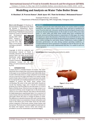
Drum Level Instrumentation Note: Photos are helpful for discussion
Photo of Serious Installation Error Code Violation and Operation Risk to Boiler
Are you having any operational issues with Water Gage Glasses on Boiler Drum applications? What instruments are installed for the display Drum Level Indication in the Control Room? Are the water level limit controls on your boiler applications working properly and tested regularly? Does the existing Drum Level Instrumentation meet the Code for the Design and Operating Pressures of your Boiler Drum? Top Questions for Users
Summary Recommendations for Drum Level Instrumentation Installations for Users • Specify or Install Code Compliant Designs • Examine Piping and isolation Valves • Consult with the Insurance Underwriter or Plant Safety Department for plant requirements, which may exceed Code minimum • Always follow the OEM maintenance instructions for the most accurate and reliable information
Summary Your time and attention to this information is appreciated, along with your contributions to Operator and Plant Safety of Power Boilers Questions