Address Accessible Memories
410 likes | 423 Vues
Address Accessible Memories. A.R. Hurson Department of Computer Science Missouri University of Science & Technology. Background Module3. Memory System Memory Requirements for a Computer An internal storage medium to store the intermediate as well as the final results,

Address Accessible Memories
E N D
Presentation Transcript
Address Accessible Memories A.R. HursonDepartment of Computer Science Missouri University of Science & Technology
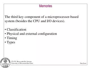
Background Module3 • Memory System • Memory Requirements for a Computer • An internal storage medium to store the intermediate as well as the final results, • An external storage medium to store input information, and • An external storage medium to store permanent results for future
Background Module3 • Memory System • Different parameters can be used in order to classify the memory systems. • In the following we will use the access mode in order to classify memory systems • Access mode is defined as the way the information stored in the memory is accessed.
Background Module3 • Memory System — Access Mode • Address Accessible Memory: Where information is accessed by its address in the memory space. • Content Addressable Memory: Where information is accessed by its contents (or partial contents).
Background Module3 • Memory System — Access Mode • Within the scope of address accessible memory we can distinguish several sub-classes; • Random Access Memory (RAM):Access time is independent of the location of the information. • Sequential Access Memory (SAM): Access time is a function of the location of the information. • Direct Access Memory (DAM): Access time is partially independent of and partially dependent on the location of the information.
Background Module3 • Memory System — Access Mode • Even within each subclass, we can distinguish several sub subclasses. • For example within the scope of Direct Access Memory we can recognize different groups: • Movable head disk, • Fixed head disk, • Parallel disk
Background Module3 • Memory System • Movable head disk: Each surface has just one read/write head. To initiate a read or write, the read/write head should be positioned on the right track first — seek time. • Seek time is a mechanical movement and hence, relatively, very slow and time consuming.
Background Module3 • Memory System • Fixed head disk: Each track has its own read/write head. This eliminates the seek time. However, this performance improvement comes at the expense of cost.
Background Module3 • Memory System • Parallel disk: To respond the growth in performance and capacity of semiconductor, secondary storage technology, introduced RAID — Redundant Array of Inexpensive Disks. • In short RAID is a large array of small independent disks acting as a single high performance logical disk.
Background Module3 • Memory System — RAID • RAID increases the performance and reliability. • Data Striping • Redundancy
Background Module3 • Memory System — RAID • Concept of data striping (distributing data transparently over multiple disks) is used to allow parallel access to the data and hence to improve disk performance. • In data striping, the data set is partitioned into equal size segments, and segments are distributed over multiple disks. • The size of segment is called the striping unit.
Background Module3 • Memory System — RAID • Redundant information allows reconstruction of data if a disk fails. There are two choices to store redundant data: • Store redundant information on a small number of separate disks — check disks. • Distribute the redundant information uniformly over all disks. • Redundant information can be an exact duplicate of the data or we can use a Parity scheme — additional information that can be used to recover from failure of any one disk in the array.
Background Module3 • Memory System — RAID • Level 0: Striping without redundancy • Offers the best write performance — no redundant data is being updated. • Offers the highest Space utilization. • Does not offer the best read performance.
Non-redundant RAID Background Module3 • Memory System — RAID • Level 0
Background Module3 • Memory System — RAID • Level 1: Mirrored — Two identical copies • Each disk has a mirror image. • Is the most expensive solution — space utilization is the lowest. • Parallel reads are allowed. • Write involves two disks, in some cases this will be done in sequence. • Maximum transfer rate is equal to the transfer rate of one disk — No striping.
Mirrored Disks Original Disks Background Module3 • Memory System — RAID • Level 1 Mirrored
Background Module3 • Memory System — RAID • Level 0 + 1: Striping and Mirroring • Parallel reads are allowed. • Space utilization is the same as level 1. • Write involves two disks and cost of write is the same as Level 1. • Maximum transfer rate is equal to the aggregate bandwidth of the disks.
Background Module3 • Memory System — RAID • Level 2: Error Correcting Codes • The striping unit is a single bit. • Hamming coding is used as a redundancy scheme. • Space utilization increases as the number of data disks increases. • Maximum transfer rate is equal to the aggregate bandwidth of the disks — Read is very efficient for large requests and is bad for small requests of the size of an individual block.
Coded Information Data Disks Background Module3 • Memory System — RAID • Level 2 Error Correcting Codes
Background Module3 • Memory System — RAID • Level 3: Bit Interleaved Parity • The striping unit is a single bit. • Unlike the level 2, the check disk is just a single parity disk, and hence it offers a higher space utilization than level 2. • Write protocol is similar to level 2 — read-modify-write cycle. • Similar to level 2, can process one I/O at a time — each read and write request involves all disks.
Data Disks Parity Disk Bit Interleaved Parity Background Module3 • Memory System — RAID • Level 3
Background Module3 • Memory System — RAID • Level 4: Block Interleaved Parity • The striping unit is a disk block. • Read requests of the size of a single block can be served just by one disk. • Parallel reads are possible for small requests, large requests can utilize full bandwidth. • Write involves modified block and check disk. • Space utilization increases with the number of data disks.
Parity Disk Data Disks Block Interleaved Parity Background Module3 • Memory System — RAID • Level 4
Background Module3 • Memory System — RAID • Level 5: Block Interleaved Distributed Parity • Parity blocks are uniformly distributed among all disks. This eliminates the bottleneck at the check disk. • Several writes can be potentially done in parallel. • Read requests have a higher level of parallelism.
Block Interleaved Distributed Parity Background Module3 • Memory System — RAID • Level 5
Background Module3 • Memory System — RAID • Level 6: P+Q Redundancy • Can tolerate higher level of failure than level 2. • It requires two check disks and similar to level 5, redundant blocks are uniformly distributed at the block level over the disks. • For small and large read requests, and large write requests, the performance is similar to level 5. • For small write requests, it behaves the same as level 2.
P+Q Redundancy Background Module3 • Memory System — RAID • Level 6
Background Module3 • Memory System — RAID
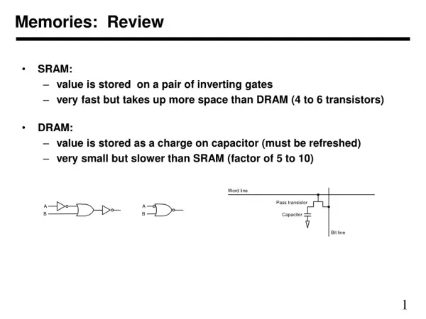
Background Module3 • Memory System — RAM • Random access memory can also be grouped into different classes • Read Only Memory (ROM) • Programmable ROM • Erasable Programmable ROM (EPROM) • Electrically Alterable ROM (EAROM) • Flash Memory
Background Module3 • Memory System — RAM • Read/Write Memory (RWM) • Static RAM (SRAM) • Dynamic RAM (DRAM) • Synchronous DRAM • Double-Data-Rate SDRAM • Volatile/Non-Volatile Memory • Destructive/Non-Destructive Read Memory
Background Module3 • Memory System • Within the scope of Random Access Memory we are concerned about two major issues: • Access Gap:Is the difference between the CPU cycle time and the main memory cycle time. • Size Gap:Is the difference between the size of the main memory and the size of the information space.
Background Module3 • Memory System • Within the scope of Random Access Memory we are concerned about two major issues: • Access Gap:Is the difference between the CPU cycle time and the main memory cycle time. • Size Gap:Is the difference between the size of the main memory and the size of the information space.
Background Module3 • Memory System • Within the scope of the memory system, the goal is to design and build a system with low cost per bit, high speed, and high capacity. In other words, in the design of a memory system we want to: • Match the rate of the information access with the processor speed. • Attain adequate performance at a reasonable cost.
Background Module3 • Memory System • The appearance of a variety of hardware as well as software solutions represents the fact that in the worst cases the trade-off between cost, speed, and capacity can be made more attractive by combining different hardware systems coupled with special features — memory hierarchy.
Background Module3 • Memory System — Access gap • Access gap problem was created by the advances in technology. In fact in early computers, such as IBM 704, CPU and main memory cycle time were identical — 12 µsec. • IBM 360/195 had the logic delay of 5 hsec per stage, a CPU cycle time of 54 hsec and a main memory cycle time of .756 µsec. • CDC 7600 had CPU and main memory cycle times of 27.5 hsec and .275 µsec, respectively.
Background Module3 • Access gap • How to reduce the access gap bottleneck: • Software Solutions: • Devise algorithmic techniques to reduce the number of accesses to the main memory. • Hardware Solutions: • Reduce the access gap. • Advances in technology • Interleaved memory • Application of registers • Cache memory
Background Module3 • Access gap — Interleaved Memory • A memory is n-way interleaved if it is composed of nindependent modules, and a word at address i is in module number i mod n. • This implies consecutive words in consecutive memorymodules. • If the n modules can be operated independently and if the memory bus line is time shared among memory modules then one should expect an increase in bandwidth between the main memory and the CPU.
Background Module3 • Access gap — Interleaved Memory • Dependencies in the programs — branches and randomness in accessing the data will degrade the effect of memory interleaving.
Background Module3 • Access gap — Interleaved Memory • To show the effectiveness of memory interleaving, assume a pure sequential program of m instructions. • For a conventional system in which main memory is composed of a single module, the system has to go through m-fetch cycles and m-execute cycles in order to execute the program. • For a system in which main memory is composed of n modules, the system executes the same program by executing ém/nù-fetch cyclesand m-execute cycles.
Background Module3 • Access gap — Interleaved Memory • The concept of modular memory can be traced back to the design of the so-called Harvard-class machines, where the main memory was composed of two modules: namely, program memory and data memory.
Background Module3 • Access gap — Interleaved Memory • It was in the design of the ILLIAC II System, where the concept of the interleaved memory was introduced. • In this machine, the memory was composed of two units. The even addresses generated by the CPU were sent to the module 0 and the odd addresses were directed to the module 1.