Utilizing Datums for Economic Process Planning
Explore single and multiple datum planning, process tolerance charts, and process boundaries for efficient economic process planning. Learn how to optimize processes for attaining best values and ensure intra-feature process planning. Follow examples for single and multi-datum scenarios to understand notations and tolerances stacking.

Utilizing Datums for Economic Process Planning
E N D
Presentation Transcript
Using Datums for Economic Process Planning Dr. R. A. Wysk IE550 Fall 2008
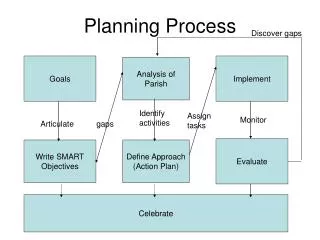
Process Planning • Single datum planning • Multiple datum plans
Process Tolerance Chart • Process Boundary Matrices Values in Process Tolerance Charts typically represent the BEST attainable values. They also represent single-feature relationships. We refer to these intra-feature process planning.
+ .005 - .0 4.0 + .005 - .005 2.0 128 A Example #1 - The simplest case; single datum, single feature A 2” piece or bar stock needs to be “faced” so that the required length and surface finish can be obtained.
Solution: In checking the work piece, datum -A- becomes the reference plan for the length, 4.0 . The OD accuracy is obtained at the rolling mill, and no OD turning is required. The length needs to be faced to final dimension. + 0.005 - 0.0
Oper. Description Machine Tool 10 Retrieve 2’’ Bar Warehouse -- 20 Cut to 4.25’’ length Cut-off saw -- 30 Face backside (remove Lathe Facing tool 1/8 ‘’ stock) 40 Flip and face front-side Lathe Facing tool 50 Remove and inspect -- -- Process Plan-Example #1
5 .005 + .005 - 0 4 + 0.01 - 0 2.0 A Example #2 -- Single datum; 2 features. 1.0 .005 Sort of like Example #1 but with a 2nd feature related to the same datum -A-.
Solution: - 4” segment is the same as in Example #1 -Addition segment requires that: -OD is reduced to 1” -Length needs to be reduced to 5 .005
C23 C12 C4 M12 M13 A The General Case and Notation. Cij is part specification or Constraints Mij is Manufacturing method were i is the datum feature, and j is the surface produced
From the part, you can see that C12 @ M12 This reads, “C12 comes directly from process M12 (our facing operation).” Also from the drawing, one can see that TC23 = TM12 + TM13 This reads, “the tolerance for feature C23 can be as large as the sum of the tolerance for producing M12 and the tolerance for producing M13” Tolerance Stacking
Notation: subscript m implies minimum M implies maximum C23m = -M12M+ M13m Let’s suppose Then TM12 = .005 TC23 = TM12 + TM13 .010 = .005 + TM13 TM13 = .005
If a negative value results then the process specification is unfeasible Since C23m = - M12M + M13m .995 = -4.005 + M13m 5.000 = M13m Set the process specifications for M13at 5.000 - 5.005
Example #4 4 .008 2 holes .250 .010 Ø .008 C A B M + + + 2.0 .01 1 B 1 1 1 Raw Material 4’’ x 2’’ x .5’’ A M Ø .01 C A B .5 .01 C .750 .010 All hole features are specified with respect to datums A-B-C and can be treated as intra-feature entities.
Example #5 .750 .010 .250 .010 B .008 C D E .01 C D E M M .5 1 1 .25 MAX + .75 D .25± .01 A .5 ± .01 2 holes E .25±.01 .50 ±.01 C C23 M12 Raw Material 4’’ x 2’’ x .5’’ M13 M14 M15
C12@ M12 TC12 = ± .01 TC23 = TM12 + TM13 C23m = -M12M + M13m .008 = -.51 + M13m From .518 = M13m TC23 = TM12 + TM13 .008 = .01 + TM13 TM13 < 0 infeasible We need to position w.r.t -E-