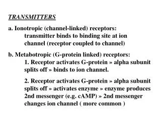
Chapter Five: Transmitters
Chapter Five: Transmitters Introduction In spite of the wide variety of uses for transmitters, from toys to broadcasting transmitters, there are only a few topologies that are used in their design Transmitter Requirements A transmitter must generate a signal with the following criteria:


Chapter Five: Transmitters
E N D
Presentation Transcript
Introduction • In spite of the wide variety of uses for transmitters, from toys to broadcasting transmitters, there are only a few topologies that are used in their design
Transmitter Requirements • A transmitter must generate a signal with the following criteria: • The correct modulation type • Must have sufficient power • Must generate at the correct carrier frequency • Should be reasonably efficient
Frequency Accuracy and Stability • The accuracy and stability of the transmitter is fixed by the carrier oscillator • Exact requirements are determined by the application of the transmitter and by regulatory agencies
Frequency Agility • Frequency agility is the ability to change operating frequency rapidly, without extensive retuning • Broadcast transmitters are rarely retuned • Other services, such as CB, require rapid and accurate retuning to other channels
Spectral Purity • Spectral purity is a measure of the spurious signals generated by a transmitter • All transmitters generate frequencies other than the carrier and the sidebands required for the modulation scheme in use • All frequencies except the assigned transmitting frequency must be filtered out to avoid interference with other transmissions
Power Output • There are a number of ways to measure transmitter power, depending upon the modulation scheme employed • Transmitters for full-carrier AM are rated in terms of carrier power • Suppressed-carrier AM transmitters are rated by peak-envelope power (PEP) • FM transmitters are rated by total power output
Efficiency • There are two important reasonsfor efficient transmitter operation: • Most obvious is energy conservation • Power that enters the transmitter but does not exit via the transmitter output is converted into heat • Large amounts of heat require significant amounts of additional hardware to remove the heat, adding to the cost of the equipment
Modulation Fidelity • An ideal communication system allows the original information signal to be recovered exactly, except for a time delay • Compression is often used to raise the overall modulation level of the signal • Compression distorts the overall dynamic range of the original signal, but results in an improved signal-to-noise ratio • Other types of distortion such as intermodulation and harmonic distortion must also be kept at a minimum
Transmitter Topology • The figure at the right shows the block diagrams of some typical transmitters • There are many varieties of transmitters but most are based upon these structures
AM Transmitters • AM transmitters are a “mature” technology, but are still in widespread use • Examples include: • Standard AM broadcast stations • CB radio • VHF aircraft radio
AM Transmitter Stages • All of the stages of a transmitter (except the power amplifier and possibly the driver) operate at low power levels • This part of the transmitter, exclusive of the power-handling stages, is called the exciter • Other transmitter components include: • The oscillator stage • The buffer and multiplier stages • The driver stage • The power amplifier/modulator
Output Impedance Matching • Most practical transmitters are designed to operate into a 50- Ohm resistive load to match the impedance of the coaxial cable that is used to carry the power to the transmitter • Transmitter output circuitry must be designed to transform the standard load resistance at the output terminal to whatever is required by the active device or devices
An AM Citizens Band Transmitter • A CB radio is always found as part of transceiver as they are economical, compact, and convenient to install and repair
Elements of a CB Transceiver • The oscillator is a frequency synthesizer • The audio circuitry consists of a microphone pre-amplifier, followed by an IC amplifier • The output circuit for the final amplifier is similar to a T network
Modern AM Transmitter Design • AM transmitters have been built since the invention of the vacuum tube and their design has changed little • There are some new approaches that are now in use • High-power AM transmitters are large and expensive because of the power handled • Recent efforts to improve AM transmitters include the development of high-power solid-state power amplifiers and the use of pulse-duration modulation and switching amplifiers in the modulation process
Modern AM Technologies • Solid-state RF power amplifiers • Pulse-duration modulators • Digital amplitude modulation
Single-Sideband AM Transmitters • A typical SSB AM transmitter block diagram is illustrated below:
Balanced Modulators for Double-Sideband Suppressed-Carrier Generation • Balanced modulators are used for DSSC generation • The output of a balanced modulator is shown here:
Generating Single-Sideband Signals • Bandpass filters may be used to filter out the unwanted sideband in an AM transmitter • The carrier is not filtered because of its large amplitude and proximity to the desired sideband • The carrier is typically nulled with a balanced modulator and then one of the sidebands is filtered
Mixing • Mixing in a DSBSC AM transmitter is done by a carrier oscillator and a balanced modulator as shown below:
Power Amplification • Power amplification in a SSB transmitter must be linear • SSB typically uses much lower power levels than are found in commercial AM broadcast transmitters as SSB is usually used for point-to-point communications
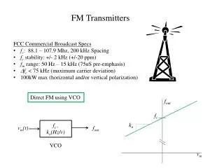
FM Transmitters • FM Transmitters typically use the following components and configurations: • Direct-FM Modulators • Frequency Multipliers • Phase-Locked Loop FM Generators • Indirect-FM Modulators • Digital FM Modulators
FM Stereo Transmitters • FM stereo uses the baseband spectrum shown here:
Transmitter Power Measurements • Power measurements are typically quite ordinary but require attention to safety in doing so • High voltages and the possibility of RF burns are dangers to the technician