Download
1 / 27
280 likes | 714 Vues
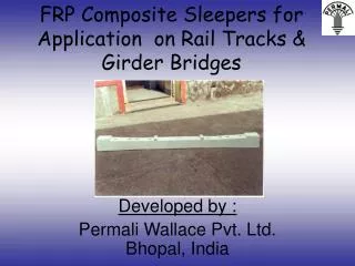
Loading Summary for a Slab on Girder Bridge According to the CAN/CSA-S6. Presented By: Andrew Chad 2006. Outline. Introduction Refresher: Limit States Load Combinations Introduce Example Bridge Simplified Method of Analysis Typ. Formatted Spreadsheet Layout

E N D
Loading Summary for a Slab on Girder Bridge According to the CAN/CSA-S6 Presented By: Andrew Chad 2006 CHBDC-S6 Bridge Loading
Outline • Introduction • Refresher: Limit States • Load Combinations • Introduce Example Bridge • Simplified Method of Analysis • Typ. Formatted Spreadsheet Layout • Load Descriptions and Design Values • Conclusion • Basically: A comprehensive load summary, takedown and analysis procedure for a new highway bridge according to CAN/CSA-S6 CHBDC-S6 Bridge Loading
Limit States • S6 Limit States Criteria: • Ultimate Limit States (ULS) • Fatigue Limit States (FLS) • Serviceability Limit States (SLS) • The chief advantages of LS Design Method are: • The recognition of the different variabilities of the various loads, for the Working Stress Method (AASHTO) encompassed both in the same factor of safety; • The recognition of a range of limit states • The promise of uniformity by the use of statistical methods to relate all to the probability of failure. CHBDC-S6 Bridge Loading
Limit States • Disadvantages: • Necessity to choose an acceptable risk of failure; for example, to quantify the acceptability of some risk that involves only structural collapse, with a risk that leads to loss of life. • The probability of failure must be applied to the number of events that may occur during the life of the structure. There is an essential difficulty in predicting an event that may not occur until 75-100 years from the point of design. CHBDC-S6 Bridge Loading
Bridge Load Types • Dead Loads (D) • Earth & Hydrostatic Pressure (E) • Secondary Prestress (P) • Live Loads (L) • Strains, Deformations and Displacement Associated Loads (K) • Wind Load on Structure (W) • Wind on Traffic (V) • Load due to Differential Settlement (S) • Earthquake Loads (EQ) • Stream and Ice Pressure, Debris Torrents (F) • Ice Accretion Load (A) • Collision Load (H) CHBDC-S6 Bridge Loading
Load Types: Superstructure Only • Dead Loads (D) • Live Loads (L) • Wind Load on Structure (W) • Wind on Traffic (V) • Earthquake Loads (EQ) CHBDC-S6 Bridge Loading
Load Combinations • Load Factors based on a service life of 75 yrs • Based on minimum reliability index of 3.75 CHBDC-S6 Bridge Loading
Load Combinations CHBDC-S6 Bridge Loading
Design Example • A “Simple” Bridge: • 2 span, 4 lane bridge • 225mm R/C Slab, on 5 continuous steel girders • Span length 20m x 2 • Typical highway overpass structure • Superstructure only! A-A 3.5m A-A CHBDC-S6 Bridge Loading
Formatted Spreadsheet • S CHBDC-S6 Bridge Loading
Simplified Method of Analysis • Simplified Method of Analysis: • The bridge width is constant • The support conditions are closely equivalent to line support, both at the ends of the bridge and, in the case of multispan bridges, at intermediate supports • For slab and slab on girder bridges with skew, the provisions of A5.1(b)(i) are met • For bridges that are curved in plan, the radius of curvature, span, and width satisfy the relative requirements of A5.1(b)(ii) • A solid or voided slab is of substantial uniform depth across a transverse section, or tapered in the vicinity of a free edge provided that the length of the taper in the transverse direction does not exceed 2.5m CHBDC-S6 Bridge Loading
Simplified Method of Analysis • Simplified Method of Analysis: • For slab-on-girder bridges, there shall be at least three longitudinal girders that are of equal flexural rigidity and equally spaced, or with variations from the mean of not more than 10% in each case • For a bridge having longitudinal girders and an overhanging deck slab, the overhang does not exceed 60% of the mean spacing betweeen the longitudinal girders or the spacing of the two outermost adjacent webs for box girders, and, also, is not more than 1.8m • For a continuous span bridge, the provisions of A5.1(a) shall apply • In the case of multispine bridges, each spin has only two webs. Also, the conditions of Cl. 10.12.5.1 shall apply for steel and steel-composite multispine bridges. CON’T CHBDC-S6 Bridge Loading
Dead Load • If bridge satisfies Cl.5.6.1.1 use “Simplified Method of Analysis” • The Beam Analogy Method: • “it is permitted to the whole of the bridge superstructure, or of part of the bridge superstructure contained between two parallel vertical planes running in the longitudinal direction, as a beam” • Take 3 interior girders & associated T.W., 9” R/C Concrete Typ. • Take 2 exterior girders & associated T.W., 9” R/C Concrete Typ. • Takes less Dead load, more live load due to deck support conditions • α Varies with different materials • 1.5 for wearing surfaces • 1.1 for steel girders 225mm CHBDC-S6 Bridge Loading
Formatted Spreadsheet • S CHBDC-S6 Bridge Loading
Live Load • Originally used Live Loads specified in AASHTO, changed in 1979 to maximum legal limits observed loads in all provinces. • Ontario uses maximum observed loads (MOL) vs. Canadian Legal Limits in other provinces • Load based on CL-W Loading • CL-W Truck as specified in Cl. 3.8.3.1 • Not less than CL-625 (kN) for national highway network. • Weight to 625kN in 2000, LL factor increased to 1.7 max • CL-W Lane Load as specified in CL. 3.8.3.2 • 9kN/m based on work done by Taylor at Second Narrows Bridge • 80% Truck load included in analysis • Dynamic Load Allowance Factors to account for more concentrated loading • Vary with amount of truck being used, size of bridge feature CHBDC-S6 Bridge Loading
Live Load • Load Cases: • 3 Load Cases ULS • Worst case of truck load, lane load including DLA • Pedestrian loads, maintenance + sidewalk loads omitted • 2 Load Cases SLS • 1 Load Case FLS • 2 lines of wheel loads in 1 lane • Multi-lane loading modification factor • When >1 lane is loaded, reduce loads per Table 3.8.4.2 • 1 lane = 1.0 • 2 lane = 0.9 • 3 lane = 0.8 CHBDC-S6 Bridge Loading
Live Load: Analysis • Longitudinal Moment • Mg = Fm * Mgavg • Where: • Fm =Amplification Factor to account for tranverse variation in max moment intensity • Mgavg = Average moment per girder by sharing equally the total moment, including multiple lane load factor • Longitudinal Moment FLS: • Loaded with 1 truck at center of 1 lane • Mg = Fm * Mgavg • Where: • Fm =Amplification Factor to account for tranverse variation in max moment intensity • Mgavg = Average moment per girder by sharing equally the total moment • Shear is Found in Similar Manner CHBDC-S6 Bridge Loading
Formatted Spreadsheet • S CHBDC-S6 Bridge Loading
Formatted Spreadsheet CHBDC-S6 Bridge Loading
Formatted Spreadsheet CHBDC-S6 Bridge Loading
Cl.-3.10 Wind Loads • “Superstructure shall be designed for wind induced vertical and horizontal drag loads acting simultaneously” • Fh=qCeCgCh • Fv=qCeCgCv • Where: • q = reference wind pressure • 1/50 for L<125m • Ce = Exposure Factor • (.1H)2 • Cg = Gust Effect Coefficient • 2.0 for L < 125m, 2.5 for more slender bridges/structures • Ch,Cv = Horizontal, Vertical drag coefficients • Bridge type not typically sensitive to wind • Not: Flexible, Slender, Lightweight, Long Span, or of Unusual Geometry. CHBDC-S6 Bridge Loading
Cl.-3.10 Wind Loads CHBDC-S6 Bridge Loading
Exceptional Loads • Low Frequency/Probability of Occurrence • Earthquake • Collision • Stream and Ice Pressure/Debris • Ice Accretion CHBDC-S6 Bridge Loading
Earthquake Loads • CAN/CSA-S6 Section 4 • Prescribes Analysis based on: • Bridge Geometry • Type • Location • Importance • Regular vs. Irregular • For a “Lifeline”, Slab on Girder, L<125m, located in Seismic Zone 4: • Minimum Analysis = Multi Mode Spectral (MM) Analysis • No analysis necessary for SOG single span bridges • Not performed due to scope • Same principles as a multi-degree of freedom structure would apply • Structure analyzed in 2 principal directions • Find principal modes, modal mass, modal participation, combine to 90% mass participation (SRSS, CQC) • Vertical motions taken by including dead load factor in ULS CHBDC-S6 Bridge Loading
Collision Loads • Superstructures to be design for “Vessel Collision” • Substructure to be designed for vehicle collision load, Vessel Collision • Not to be included in spreadsheet, see S6-3.14 CHBDC-S6 Bridge Loading
Conclusions • C.H.B.D.C. based on O.H.B.D.C. which was revolutionary in its use of LSD and design vehicle based on legal limits • C.H.B.D.C. complicated but well written code • Many loads were omitted for this “simple” bridge, only a basic design/analysis was performed • Easy to get confused, make “small” mistakes • Simplified methods of design are a good start, although still somewhat tricky. CHBDC-S6 Bridge Loading
Conclusions QUESTIONS? CHBDC-S6 Bridge Loading