Verification Implementation: GPM Navigator Software Case Study
Explore the successful implementation of the GPM Navigator Software through a case study approach, focusing on the role of PBRA & SRM, lessons learned, and future work. Discover insights into maintaining health and safety, propulsion systems, and test capabilities.


Verification Implementation: GPM Navigator Software Case Study
E N D
Presentation Transcript
Verifying Implementation Prototype Independent Test Capability Team Bill Stanton Jarrod Petersavage Justin Morris Steven Seeger Mike Wise
OBJECTIVES • CASE STUDY APPROACH • ROLE OF THE PBRA & SRM • CASE STUDY RESULTS • LESSONS LEARNED • FUTURE WORK
CASE STUDY APPROACH Navigator Software on GPM Project
WHAT DID WE DO? • Chose a Project GPM • Examined PBRA Results • GPM PBRA Profile: March 5, 2009 • GPM PBRA-Lite: May 28, 2009 • Chose a small example Navigator Software • Requirements: • Code is Available • Some Documentation Available • Supporting Tool(s) Available • Modeling Artifacts Available • Successfully Run Code Executed using EDGE IDE with SimTest Simulator • Develop and Execute Test Cases using Sequences from GPM SRM (Working)
Role of the PBRA & SRMIdentify Target Behavior(s) GPM PBRA ProfileMarch 5, 2009, Macaulay, Dunkerley System Capabilities J1: Launch and Achieve Initial Orbit J2: Checkout Spacecraft J3: Fly in Required Orbits J4: Obtain Science Data J5: Maintain Health and Safety of Spacecraft J6: Process Science Data J7: Decommission Spacecraft J5 J4 J2 J1 J7 J3 J6 Impact
Role of the PBRA & SRMIdentify Target Behavior(s) “Maintain Health and Safety of Spacecraft Activity Diagram” None H H H H H H Maintain Propulsion System
Role of the PBRA & SRMIdentify Target Behavior(s) Maintain Propulsion System Activity Diagram M Determine Position & Delta-V H M M H H L H H M M
Role of the PBRA & SRMIdentify Target Behavior(s) • Determine Position and Delta-V • Behavior is implemented in the GPS Navigator • The SC determines its position using GPS position information.
Case Study Results Accomplishments Future Work • Identified a capability using PBRA & SRM to drive Verification Implementation Activities (Case Study) • Executed Navigator Flight Software using a trial version of a COTS toolset in 2 months • Duration includes obtaining all required tools and artifacts and configuring the environment • Develop serial interface to provide conduit for testing • Utilize Elaborated Sequence Diagrams (to be developed by SRMV PL) to drive test cases
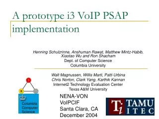
Navigator Software Simulation • Navigator software runs on a FreeScale ColdFire 5307. • On GPM, the Navigator is part of GN&C and connects to C&DH via RS-422. • GPM has two Navigator units, but we only need to test one. • Initial trial run used EDGE Development suite from Mentor Graphics. • Compiled code as x86 without Nucleus OS code. • Nucleus runtime provided by simtest. 14
Navigator Commands • All Navigator commands and responses are transmitted over RS-422. • ITC team determined that Navigator would be a good place to start because sending and receiving serial data is not difficult. • Navigator commands over serial include read and write memory, patience, and ephemeris data. • Easy proof of concept with simple write and read-back operation. • Can expand simulation further with more complex commands. • CCSDS message format. 15
Issues with Hardware Simulation • Navigator has an RF board that receives GPS signals. • Difficult to simulate. • Developer usescomplex hardwareand softwaresimulation solution. 16
Software Simulation End Goal • Run binaries provided by vendors on an instruction set simulator. • No need to compile Navigator software for x86. • No chance of results varying by build process. • More hardware interaction. • Simulation • Real hardware • Headless operation with all simulations driven by test scripts. 17
Lessons Learned • Working with Trial Versions of Tools often Proves Difficult • Vendor Support • 30-day to 60-day Trial Window • Limited Tool Capabilities • Importance of Communications between Product Lines • Modeling Artifacts help drive Verification Implementation Activities • Importance of SRMV and Verification Task Scheduling • Initial setup time will vary depending on test environment and requirements • Project Leads & Product Lines need to identify Verification Implementation targets early in lifecycle to allow time for tool acquisition, development time, and training • Leveraging of Developer’s Capabilities may prove Beneficial Parallel Activities
Parallel ActivitiesOther Items being worked by the ITC TeamNot scope of presentation – Information Sharing • SoftSim • All-digital system simulation with flight-like interfaces • Juno and GRAIL missions • VxWorks • Utilized by almost all Science missions • ITC is obtaining trial version, inquiring about licensing, and training • License required to support SoftSim testing
Provides Additional Capability“Static versus Dynamic Analysis”