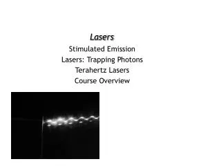
Robust Stabilized CO 2 Lasers with Line Tracker
130 likes | 306 Vues
Robust Stabilized CO 2 Lasers with Line Tracker. Access Laser Company where innovation never stops. Main Features. Offered with stabilized or grating tuned lasers Robust stabilization allows field applications where ambient environment changes.

Robust Stabilized CO 2 Lasers with Line Tracker
E N D
Presentation Transcript
Robust Stabilized CO2 Laserswith Line Tracker Access Laser Company where innovation never stops www.accesslaserco.com ♦ 5603 47th Ave NE, Marysville, WA 98270, USA ♦ 360-651-6141
Main Features • Offered with stabilized or grating tuned lasers • Robust stabilization allows field applications where ambient environment changes. • Stabilization without the side-effect of “chirping” inherent with the traditional dithering scheme. • Power, spectrum, longitudinal mode and transverse modes are all stabilized at the same time. • Maintains the stability of laser at any power level that is independently adjusted. • Optimized sampling scheme depends on specifics of the laser model. Contact factory for details. www.accesslaserco.com ♦ 5603 47th Ave NE, Marysville, WA 98270, USA ♦ 360-651-6141
Laser Beam sampler LT Controller The Idea: Closed loop feedback control • Laser output is sampled and turned into an electronic signal • Signal is compared by the controller to the set value • Controller makes a decision whether to change the laser resonator. • Command is sent to laser to change or maintain the laser resonator. • Different from the traditional “dithering” approach: Piezo only moves to correct the residual drift of the well-stabilized resonator. There is no artificial frequency and power fluctuation introduced by the “dither.” www.accesslaserco.com ♦ 5603 47th Ave NE, Marysville, WA 98270, USA ♦ 360-651-6141
~10/% >10/% Piezo moves around the set point to stabilize length of resonator. The correct working point for grating tuned lasers is at about 10% below the peak value and more than 10% above the valley, to provide enough room for correction. Find the RightWorking Point - Grating Tuned Lasers www.accesslaserco.com ♦ 5603 47th Ave NE, Marysville, WA 98270, USA ♦ 360-651-6141
RF power input Signal output to LT Controller Input from LT controller 45 deg beam sampler assembly Lasy-4S with Line Tracker, an example www.accesslaserco.com ♦ 5603 47th Ave NE, Marysville, WA 98270, USA ♦ 360-651-6141
RF power input Small angle Beam sampler assembly Input from LT controller Signal output to LT Controller Lasy-4S with Line Tracker, small angle sampling www.accesslaserco.com ♦ 5603 47th Ave NE, Marysville, WA 98270, USA ♦ 360-651-6141
The LT Controller • Push buttons (black): • Mode SEL: Switch to pen loop or close loop • Profiling: scan for a profile of power pattern • Scaling: Auto gain control • Up: Open loop mode- manually increase driving voltage. Close loop mode-manually increase power. • Down: Open loop mode-manually decrease driving voltage. Close loop mode- manually decrease power. • LED’s • Top red: Power indicator • Closed Loop: Red-searching, Green-locked. • Open Loop: Lights up in open loop mode • Profiling: Blinks during profiling • Signal LVL: fast blinks all the time. Green-power too low; Red- Power too high;Amber-Power OK www.accesslaserco.com ♦ 5603 47th Ave NE, Marysville, WA 98270, USA ♦ 360-651-6141
RS-232 to computer DB-9 male Input from Sampler BNC HV to piezo on laser OEM interface/ test connections DB-9 male Input from 12 V DC supply LT Controller connections www.accesslaserco.com ♦ 5603 47th Ave NE, Marysville, WA 98270, USA ♦ 360-651-6141
Pin-5 Pin-1 Pin-1: HV monitor (analog) Pin-2: Scale-Over (digital) Pin-3: Mode (digital) Pin-4: Tracking (digital) Pin-5: Ground Pin-6: Scale-Under (digital) Pin-7: Power (Analog) Pin-8: Searching (digital) Pin-9: reserved Note: All pins are output Pin-9 Pin-6 Monitoring Status of Laser and LT Controller www.accesslaserco.com ♦ 5603 47th Ave NE, Marysville, WA 98270, USA ♦ 360-651-6141
Press this start arrow to activate the program It is a good idea to keep the power level at 700 or higher for high system resolution. Select the appropriate serial port before activating the program Computer interface: Line Tracker Software NOTE: All functions of the LT controller are available here in the Line Tracker software. Some functions of the Line Tracker software are not available in the LT controller. www.accesslaserco.com ♦ 5603 47th Ave NE, Marysville, WA 98270, USA ♦ 360-651-6141
Both power and voltage are set to a full range of 0 to 1024, arbitrary units. When AutoSave is on files are saved as filled, with a time stamp in the file name. Data files are .csv format for easy importing into Excel. File size indicates the number of data sets per file. Maximum 3600. Laser is stabilized in the close-loop mode by moving the length of the resonator along the falling edge or the rising edge. If manual setting is not entered by pressing the return key it will not take effect Scale factor in effect Make sure to select the appropriate serial port before starting operation Computer interface /data logging www.accesslaserco.com ♦ 5603 47th Ave NE, Marysville, WA 98270, USA ♦ 360-651-6141
After profiling this yellow setting line becomes a cross. Move the cross to approximately 10% below the desired peak on the power curve, select the appropriate edge, then press the “start tracking” button. The laser will start to be tracked and stabilized. Notice that the piezo voltage (blue curve) moves up and down to keep the laser power (red curve) steady. Close loop operation www.accesslaserco.com ♦ 5603 47th Ave NE, Marysville, WA 98270, USA ♦ 360-651-6141
With this version of software chose Closed loop on the control box and the system starts to search for a lockable positionWhen it finds a lockable position it goes into closed-loop mode. When the piezo reaches end of travel it will restart searching for a lockable position. During this time an “out of lock” signal is given from the controller and displayed on the screen.This version of software does not allow control from computer. All controls are performed from the controller box. The software allows for display and data logging. Line Tracker- Auto Version www.accesslaserco.com ♦ 5603 47th Ave NE, Marysville, WA 98270, USA ♦ 360-651-6141