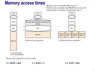
DIRECT MEMORY ACCESS
DIRECT MEMORY ACCESS. CS 147 Thursday July 5,2001 SEEMA RAI. OVERVIEW . Introduction Implementing DMA in a computer system Data transfer using DMA controller Internal configuration of a DMA controller Process of DMA transfer DMA transfer modes Modification of the CPU to work with DMA

DIRECT MEMORY ACCESS
E N D
Presentation Transcript
DIRECT MEMORY ACCESS CS 147 Thursday July 5,2001 SEEMA RAI
OVERVIEW • Introduction • Implementing DMA in a computer system • Data transfer using DMA controller • Internal configuration of a DMA controller • Process of DMA transfer • DMA transfer modes • Modification of the CPU to work with DMA • Summary
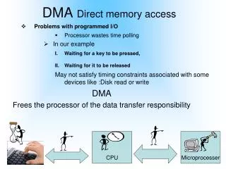
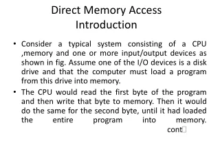
Direct Memory Access • Introduction • An important aspect governing the Computer System performance is the transfer of data between memory and I/O devices. • The operation involves loading programs or data files from disk into memory, saving file on disk, and accessing virtual memory pages on any secondary storage medium. cont
Consider a typical system consisting of a CPU ,memory and one or more input/output devices as shown in fig. Assume one of the I/O devices is a disk drive and that the computer must load a program from this drive into memory. • The CPU would read the first byte of the program and then write that byte to memory. Then it would do the same for the second byte, until it had loaded the entire program into memory. cont
This process proves to be inefficient. Loading data into, and then writing data out of the CPU significantly slows down the transfer. The CPU does not modify the data at all, so it only serves as an additional stop for data on the way to it’s final destinaion. • The process would be much quicker if we could bypass the CPU & transfer data directly from the I/O device to memory. • Direct Memory Access does exactly that.
Implementing DMA in a Computer System • A DMA controller implements direct memory access in a computer system. • It connects directly to the I/O device at one end and to the system buses at the other end. It also interacts with the CPU, both via the system buses and two new direct connections. • It is sometimes referred to as a channel. In an alternate configuration, the DMA controller may be incorporated directly into the I/O device.
Data Transfer using DMA Controller • To transfer data from an I/O device to memory, the DMA controller first sends a Bus Request to the CPU by setting BR to 1. When it is ready to grant this request, the CPU sets it’s Bus grant signal, BG to 1. • The CPU also tri-states it’s address,data, and control lines thus truly granting control of the system buses to the DMA controller. • The CPU will continue to tri-state it’s outputs as long as BR is asserted. cont
Internal Configuration • The DMA controller includes several registers :- • The DMA Address Register contains the memory address to be used in the data transfer. The CPU treats this signal as one or more output ports. • The DMA Count Register, also called Word Count Register, contains the no. of bytes of data to be transferred. Like the DMA address register, it too is treated as an O/P port (with a diff. Address) by the CPU. • The DMA Control Register accepts commands from the CPU. It is also treated as an O/P port by the CPU. cont
Although not shown in this fig., most DMA controllers also have a Status Register. This register supplies information to the CPU, which accesses it as an I/P port.
Process of DMA Transfer • To initiate a DMA transfer, the CPU loads the address of the first memory location of the memory block (to be read or written from) into the DMA address register. It does his via an I/O output instruction, such as the OTPT instruction for the relatively simple CPU. • It then writes the no. of bytes to be transferred into the DMA count register in the sane manner. • Finally, it writes one or more commands to the DMA control register. cont
These commands may specify transfer options such as the DMA transfer mode, but should always specify the direction of the transfer, either from I/O to memory or from memory to I/O. • The last command causes the DMA controller to initiate the transfer. The controller then sets BR to 1 and, once BG becomes 1 , seizes control of the system buses.
DMA Transfer Modes Modes vary by how the DMA controller determines when to transfer data, but the actual data transfer process is the same for all the modes. • BURST mode • Sometimes called Block Transfer Mode. • An entire block of data is transferred in one contiguous sequence. Once the DMA controller is granted access to the system buses by the CPU, it transfers all bytes of data in the data block before releasing control of the system buses back to the CPU. • This mode is useful for loading programs or data files into memory, but it does render the CPU inactive for relatively long periods of time. cont
CYCLE STEALING Mode • Viable alternative for systems in which the CPU should not be disabled for the length of time needed for Burst transfer modes. • DMA controller obtains access to the system buses as in burst mode, using BR & BG signals. However, it transfers one byte of data and then deasserts BR, returning control of the system buses to the CPU. It continually issues requests via BR, transferring one byte of data per request, until it has transferred it’s entire block of data. cont
By continually obtaining and releasing control of the system buses, the DMA controller essentially interleaves instruction & data transfers. The CPU processes an instruction, then the DMA controller transfers a data value, and so on. • The data block is not transferred as quickly as in burst mode, but the CPU is not idled for as long as in that mode. • Useful for controllers monitoring data in real time.
TRANSPARENT Mode • This requires the most time to transfer a block of data, yet it is also the most efficient in terms of overall system performance. • The DMA controller only transfers data when the CPU is performing operations that do not use the system buses. • For example, the Relatively simple CPU has several states that move or process data solely within the CPU: NOP1: (No operation) LDAC5: ACDR cont
JUMP3: PCDR,TR CLAC1: AC0, Z1 • Primary advantage is that CPU never stops executing its programs and DMA transfer is free in terms of time. • Disadvantage is that the hardware needed to determine when the CPU is not using the system buses can be quite complex and relatively expensive.
Modification of the CPU to work with DMA • Addition of control input BR and control output BG, along with the logic to generate BG. • The logic depends on when the designer wants the CPU to be able to grant control of the system buses to the DMA controller. • Most CPU’s allow DMA requests to be granted after the instruction has been fetched; after it has been decoded, after it’s operations have been fetched ; after the instruction has been executed, and after it’s results have been stored. cont
Following example modifies the relatively simple CPU so that it serves DMA requests only at the beginning of the fetch cycle, immediately after the instruction has been executed. • Because BG is latched, it’s operations can be expressed using RTL code. • When CPU enters FETCH1, if BR=1, it sets BG to 1;it remains in FETCH1 until BR is 0. • If BR is 0, it sets BG to 0 and perorms the other micro-operations associated with state FETCH1. • The RTL code is cont
BR ^FETCH1: BG1 BR`^FETCH1: BG0,(micro-operations of FETCH1) • The two micro-operations that load BG could be combined into a single micro-operations, yielding the RTL code FETCH1: BGBR BR`^FETCH1: (micro-operations of FETCH1) • The control unit is modified to implement the loop from FETCH1 back to itself while BR is 1. • The figure shows the modification needed for the state diagram. • Finally the CPU must tri-state it’s outputs whenever the DMA controller has access to the bus. Tri-state buffers are added to the address ouputs A[15..0] and all control outputs. The data input/ouput signals already have tri-state buffers.
The address and control outputs should be enabled at all times, except when the DMA controller has access to the system buses. This only occurs when BG=1, so BG` can be used to enable the address and control bus buffers.
Summary • Advantages of DMA • Computer system performance is improved by direct transfer of data between memory and I/O devices, bypassing the CPU. • CPU is free to perform operations that do not use system buses. • Disadvantages of DMA • In case of Burst Mode data transfer, the CPU is rendered inactive for relatively long periods of time.