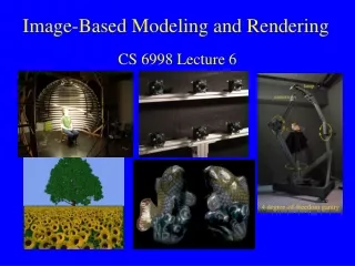
Art-Based Rendering of Fur, Grass, and Trees
Art-Based Rendering of Fur, Grass, and Trees Michael A. Kowalski, Lee Markosian, J.D. Northrup, Lubomir Bourdev, Ronen Barzel Overview Introduction Prior Work Method Results / Conclusion Introduction

Art-Based Rendering of Fur, Grass, and Trees
E N D
Presentation Transcript
Art-Based Rendering of Fur, Grass, and Trees Michael A. Kowalski, Lee Markosian, J.D. Northrup, Lubomir Bourdev, Ronen Barzel
Overview • Introduction • Prior Work • Method • Results / Conclusion
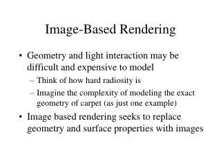
Introduction • “Any art student can rapidly draw a teddy bear or a grassy field. But for computer graphics, fur and grass are complex and time consuming.”
Introduction • The Problem • How can we use current 3D graphics to create the effectiveness and persuasiveness or an artist’s few stroke drawings?
Introduction • Motivation • Expand 3D graphics by using techniques for depicting complexity from art and illustration.
Introduction • Goals • Give designer of a scene control over the style of rendering. • Ease the burden of modeling complex scenes by treating the rendering strategy as an aspect of modeling. • Provide interframe coherence for the kinds of stylized renderings developed.
Introduction • Solution • To simulate making strokes on a 2D surface, they propose stroke-based textures.
Prior Work • Particle Systems • Reeves introduced particle systems that he used to create trees, fireworks, and other complex images. • Alvy Ray Smith used particle systems and L-systems to create graftals that he used to create more accurate biological structures
Prior Work • Particle System • Cartoon Tree by Badler and Glassner is the direct precursor that uses fractals and graftals to create surfaces through an implicit model that produce data.
Prior Work • Stroke Placement • Difference Image by Salisbury et al. had a stroke-placing algorithm that was modified to place procedural texture elements at specific areas.
Prior Work • Stroke Placement • Winkenbach and Salesin used “indication” for pen-and-ink rendering. • Strothotte et al. wrote about artistic styles that result in specific effects or perceptions.
Prior Work • Particle Based Strokes • Meier provided two insights in her particle-based brush stokes method. • Using particles to govern strokes in her Monet works showed that not all complexity need be geometric. • Optimal particle on object hybrid space technique
Prior Work • NPR • Built on earlier efforts at interactive frame rates. More than one style.
Method • System Framework • Use OpenGL to render polyhedral models. • Models are divided into surface regions (patches). • Each patch has one or more procedural texture.
Method • System Framework • Reference Images: they are off-screen renders of scene that are rendered into textures • Use 2: • Color Reference image • ID reference image.
Method • System Framework • Color Reference Image • An active texture of each patch will render into this image in the appropriate manner. (How to draw and where to draw tufts, grass…)
Method • System Framework • ID Reference Image • Triangles or edges are each rendered with a color that uniquely identifies that triangle or edge. • Then these are edges or triangles are stored in the patches that contains that edge or triangle.
Method • Graftal Textures • Procedurally place fur, leaves, grass or other elements. • Two Rules: • Must be placed with controlled density • Seem stick to the surface.
Method • Placing Graftals • Use Difference Image Algorithm where a blurred image of the stroke is subtracted from a difference image. • At each subsequent step, they search the pixel most in need of darkening. • This handles the controled density for graftal placement.
Method • Graftal Placement • To control density each graftal texture draws its patch into the color reference image so that darker tones correspond to denser graftal areas. • Darker in silhouettes in this image.
Method • Graftal Placement • Use the ID Reference image to convert 2D screen position to 2D position on a surface. (Constant time)
Method • Graftal Placement • Frame to frame • In first frame graftals are place according to the Difference Image Algorithm • Each successive frame try to use prior graftal texture • If the old can not be used, the Difference Image Algorithm is used to place new graftals
Method • Graftal Placement • A graftal can be not selected for two reasons • It is not visible, it is zoomed too far out. • Insufficient desire for it to be placed in the new image. • Use a bucket sort to find greatest desire (Constant Time)
Method • Subtracting Blurred Image • This determines the desire of a graftal. • Graftals subtract a blurred image of themselves from the difference image. (Gaussian Dot) • Pixels in the desire image are coded with values from zero to one. This is associated with its screen space area based on their volume.
Method • Subtracting Blurred Image • Graftals can scale their geometry and volume to maintain desired density and size.
Method • Computing Scale Factors • Convert Object space length L to screen space length s every frame. • Uses scale factor r composed of 2 users specified variables • d: the screen space length • Vo: corresponding volume
Method • Computing Scaling Factors • Volume per frame is calculated
Method • Computing Gaussian Dot of Graftal • Calculate the gaussion dot using this equation. • The Pixels are then subtracted from the desired image. The desire should equal the volume. (Optimal)
Method • Displaying Graftals • If the desire is less than the volume of a graftal, the LOD of the graftal is reduced. This prevents popping.
Method • Drawing the Tuft • They use a tapering shape guided by a central spine. The tapered values are stored in an array. • To orient the tufts, the compute the dot product of the view vector and the normal. This determines the LOD. • The tufts are drawn in an almost orthogonal to the view and pointed down or clockwise.
Results / Conclusions • They were able to produce scenes with simple geometry models. • They were able to produce interactive scenes on higher-end PCs. • Problem • Its still easy to create cluttered graftals from the DIA at a frame to frame.
Results / Conclusions • Future Work • Use of fading and alpha blending to fade out graftals. • Depends highly on style being used. • Silhouettes seem to be missing some graftals because they are so faded. • Use another call to the DIA for a back-faced and front-faced graftals. This would reduce the popping of graftals along the silhouettes.
Results / Conclusions • Future Work • Static graftal placement • Draw in a view dependent manner with lower detail the farther a graftal is away from the silhouette. • Problem is that you can not zoom in and out too far. • A fix they have planned to priority values from 0 to 2. They will do work on the graftals with the lowest priority value first using the DIA. Then the next are drawn.
Results / Conclusions • Future Work • Static Graftal Placement • Successful for single instances, but has not been tested for landscapes yet.
Questions??? • ??????
References • [1] Norman I. Badler and Andrew S. Glassner. 3D object modeling. • In SIGGRAPH 97 Introduction to Computer Graphics Course Notes. • ACM SIGGRAPH, August 1997. • [2] OpenGL Architecture Review Board. OpenGL Reference Manual, • 2nd Edition. Addison-Wesley Developers Press, 1996. • [3] J. D. Foley, A. van Dam, S. K. Feiner, and J. F. Hughes. Computer • Graphics: Principles and Practice. Addison-Wesley, Reading, MA, • 2nd edition, 1992. • [4] Dr. Seuss (Theodor Geisel). The Lorax. Random House, New York, • 1971. • [5] Dr. Seuss (Theodor Geisel). The Foot Book. Random House, New • York, 1988. • [6] Amy Gooch, Bruce Gooch, Peter Shirley, and Elaine Cohen. A nonphotorealistic • lighting model for automatic technical illustration. In • SIGGRAPH 98 Conference Proceedings, pp. 447–452. ACM SIGGRAPH, • July 1998. • [7] Geoffrey Hayes. Patrick and Ted. Scholastic, Inc., New York, 1984. • [8] Lee Markosian. Art-based Modeling and Rendering for Computer • Graphics. PhD thesis, Brown University, November 1999 (expected • completion). • [9] LeeMarkosian, JonathanM. Cohen, Thomas Crulli, and JohnHughes. • Skin: A constructive approach to modeling free-form shapes. In • SIGGRAPH 99 Conference Proceedings. ACM SIGGRAPH, August • 1999. • [10] LeeMarkosian, MichaelA. Kowalski, Samuel J. Trychin, Lubomir D. • Bourdev, Daniel Goldstein, and John F. Hughes. Real-time nonphotorealistic • rendering. In SIGGRAPH 97 Conference Proceedings, pp. • 415–420.ACM SIGGRAPH, August 1997. • [11] Barbara J. Meier. Painterly rendering for animation. In SIGGRAPH • 96 Conference Proceedings, pp. 477–484.ACMSIGGRAPH, August • 1996. • [12] W. T. Reeves. Particle systems – a technique for modeling a class of • fuzzy objects. ACM Trans. Graphics, 2:91–108,April 1983. • [13] William T. Reeves and Ricki Blau. Approximate and probabilistic algorithms • for shading and rendering structured particle systems. In • SIGGRAPH 85 Conference Proceedings, pp. 313–322. ACM SIGGRAPH, • July 1985. • [14] Michael P. Salisbury,Michael T.Wong, John F. Hughes, and David H. • Salesin. Orientable textures for image-based pen-and-ink illustration. • In SIGGRAPH 97 Conference Proceedings, pp. 401–406. ACM SIGGRAPH, • August 1997. • [15] Alvy Ray Smith. Plants, fractals and formal languages. In SIGGRAPH • 84 Conference Proceedings, pp. 1–10. ACMSIGGRAPH, July 1984. • [16] T. Strothotte, B. Preim, A. Raab, J. Schumann, andD. R. Forsey.How • to render frames and influence people. In Computer Graphics Forum, • volume 13, pp. 455–466. Eurographics, Basil Blackwell Ltd, 1994. • Eurographics ’94 Conference issue. • [17] Georges Winkenbach and David H. Salesin. Computer–generated • pen–and–ink illustration. In SIGGRAPH 94 Conference Proceedings, • pp. 91–100.ACM SIGGRAPH, July 1994. • 6 • 438