Image-Based Rendering
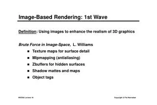
Image-Based Rendering. Computer Graphics. Image-Based Rendering. Image-Based Rendering is a series of techniques that all involve 2D images as the primary data rather than 3D models The main goal is to decouple rendering time from scene complexity

Image-Based Rendering
E N D
Presentation Transcript
Image-Based Rendering Computer Graphics
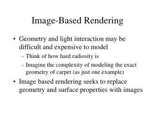
Image-Based Rendering • Image-Based Rendering is a series of techniques that all involve 2D images as the primary data rather than 3D models • The main goal is to decouple rendering time from scene complexity • Rendering time is instead proportional to the number of pixels rendered • Techniques we will examine: • Billboards • Depth Images • Lumigraphs
IBR – Billboards • An image is rendered to a polygon facing the viewer • The texture map is considered the 3D entity rather than as a map that control colors over an actual 3D surface • As the camera moves the billboard orientation changes to match • Needs to be updated often maintain realism • Error terms can be calculated to determine when the change should occur (i.e. when the imposter is invalid)
IBR – Billboards • There are several different types of Billboards: • Screen, World, or Axial aligned • The differences between them involve how the billboard is allowed to rotate • In general, think of the billboard as always facing up with their normal being the negated view vector • Of course, the illusion is then destroyed if the camera flies over the top of the billboard
IBR – Billboards • Billboards generally refer to the notion of a image pasted on a polygon that rotates to match the viewer’s position • There are also related concepts such as impostors and sprites • Often these don’t rotate, but instead are warped (affine transformation) to a new location • Of course, this usually requires some depth information (will discuss later)
IBR – Billboards • Used in games/VE for creating objects such as trees or clouds • Alpha blending of the texture maps allows the background to show through • http://www.cs.unc.edu/~harrism/clouds/
IBR – Billboards • Also used to create special effects in games • Explosions, lens flare, laser trails
IBR – Billboards • Lens flare is what you get when you look directly into a light source: +
IBR – Billboards • Lasers can be simulated using 2 orthogonal billboards: +
IBR – Billboards • The dual billboards need to be rotated in such as way as to keep the cross section perpendicular with the viewing plane
IBR – Billboards • Among the disadvantages of billboards is that they cannot produce motion parallax • Objects that are closer to the viewer move more as the viewer moves from sideways
Full IBR • Billboards were a way to place IBR segments into a traditional geometry rendering process • The following techniques render the entire scene using IBR without using any traditional geometry • To do this we usually add some form of depth information to our images • Makes them more than 2D • Several of the techniques discussed are 2½D representations
Full IBR • Some common forms of full IBR: • Image Layers • Depth Images • Layered Depth Images (LDI) • Lumigraphs
IBR – Image Layers • The entire image is divided into layers • A special image segmentor is used • Each layer has a single depth value associated with it • Effectively the image is a discrete version of 3D screen space • Similar to traditional cell animation • Layers can be warped using an affine transformation to adjust to new viewpoints
IBR – Image Layers • Each layer is rendered independently • Often using different resolutions
IBR - Depth Images • Depth images contain a depth value per pixel • Note that this is fairly easy to obtain with laser range finder/camera setups • Obviously these images look great if viewed from the same place as the picture was originally taken • However, the goal is to use the depth information to extrapolated an image at a new viewpoint from the given reference image
IBR - Depth Images • Given the original reference image and the position/orientation it was taken from, we can produce a warped image using the following: (r11x + r12y + r13) Z(x, y) + txX’ = ----------------------------------- (r31x + r32y + r33) Z(x, y) + tz (r21x + r22y + r23) Z(x, y) + tyY’ = ----------------------------------- (r31x + r32y + r33) Z(x, y) + tz Where the r’s are the 3x3 rotation matrix of the camera, the t’s are the translation of the camera and the Z’s are the depth information in the reference image
IBR - Depth Images • A sample of a generated image • Reference image is on the left • Generated image is on the right • The camera was translated to the right
IBR - Depth Images • Another example: reference image on left
IBR - Depth Images • There are two major problems that occur with depth images: • Image folding • Holes
IBR - Depth Images • Image folding occurs when more than one pixel in the reference image maps onto the same position in the extrapolated image • See figure p.553 games book • Which of the two reference pixels should go in the extrapolated image? • Obviously the closer one
IBR - Depth Images • However, determining the “closer one” requires an extra “Z-buffer” in the extrapolated image to hold the depth info and an extra calculation of Z(x’,y’) from Z(x,y) • Normally only the reference image holds depth info • There is also an algorithm by McMillan that specifies a unique evaluation order for computing the warp function such that surfaces can be drawn in a back to front order • Enables use a simple painters algorithm and avoids the storage of extra Z values
IBR - Depth Images • Holes are the other Depth Image problem • Holes in the extrapolated image occur when information occluded in the reference image is required in the extrapolated image • See figure p.533 games book
IBR - Depth Images • This is a much more severe problem than image folding • There is no way to recover the needed information since it doesn’t exist in the reference image • Thus, “holes” occur the extrapolated image • See color plate 19.12 in game book
IBR - Depth Images • More examples of holes
IBR - Depth Images • The standard way to fix holes is to simply fill them with colors interpolated from the neighboring pixels • The underlying cause of holes is that the reference view is “too far away” from the extrapolated view • This implies another way of addressing the holes problem: use multiple references images • Extrapolated images from each of the reference images • Composite the results
IBR - Depth Images • Holes can also be created by foreshortening • A section in the extrapolated image covers more area (pixels) than we have available in the reference image • See figure p.553 game book • Rotation of the camera is a large cause of this • See color plate 19.12
IBR - Depth Images • Note that there are issues with view-dependent lighting for Depth Images • It doesn’t handle it • Of course, given the hole/image folding problems that occur if the extrapolated view is too far away from the reference view, we actually have the geometry breaking down at least as fast as the specular lighting would
IBR - LDI • A Layered Depth Image is simply a Depth Image with multiple depths at each pixel • The depths of all the objects that a ray through the pixel in question intersects • See figure p.556 from game book
IBR - LDI • Fixes most of the problems with holes that normal depth images have • The missing information is contained in the LDI • Results: • Show demo of sunflowers • Paper reference: http://grail.cs.washington.edu/projects/ldi/ldi.pdf
IBR - LDI • How does one obtain a LDI? • Normal Depth Images are easy to obtain because of the widespread use of laser range finders, but they don’t work for LDIs • One solution is to use a modified raytracer • Shoot rays out through each pixel and record where they hit, but then instead of reflecting them as in a normal raytracer, penetrate the rays through the objects and continue on the same path
IBR - LDI • Another way to create an LDI image is to take N images from different viewpoints and warp them into a single viewpoint • If more than one image has a depth value that maps to the same pixel in the LDI then their depth values should be properly sorted
IBR - LDI • An interesting use of LDI as a hybrid method in a standard triangle renderer is to use them to represent portals • Take multiple images through the portal from different locations • Warp them into a single LDI that represents the portal from a specific view • Use real-time LDI warping to generate any potential viewpoint through the portal • Not just the original viewpoints • Will have problems with dynamically moving objects through the portal
IBR – Light Fields/Lumigraphs • Lumigraphs and Light Fields are related approaches that both pre-calculate all the lighting in the photographed scene • Again no triangle geometry • Although Lumigraphs can use some geometry info • New scene is then rendered from a new viewpoint and the lighting looks correct • What exactly is a Light Field?
IBR – Light Fields/Lumigraphs • http://graphics.stanford.edu/software/lightpack/lifmpegs.html
IBR – Light Fields/Lumigraphs • The major problems with this approach: • It is difficult to capture the light fields • Their storage cost is huge! • Does not require depth information!