Download

1 / 23
230 likes | 357 Vues
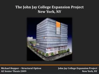
Nicholas Reed Structural Option Seneca Allegany Casino Hotel Addition AE Senior Thesis 2013. Courtesy of Jim Boje , PE. Building Introduction Existing Structure Thesis Goals Structural Depth Architectural Study Conclusion Q&A. Salamanca, NY. Bing Maps. Casino Event Center Hotel

E N D
Nicholas Reed Structural Option Seneca Allegany Casino Hotel Addition AE Senior Thesis 2013 Courtesy of Jim Boje, PE
Building Introduction Existing Structure Thesis Goals Structural Depth Architectural Study Conclusion Q&A Salamanca, NY Bing Maps Casino Event Center Hotel Parking Deck Wikipedia
Building Introduction Existing Structure Thesis Goals Structural Depth Architectural Study Conclusion Q&A Project Team Building Statistics Owner: Seneca Gaming Corporation Architect: JCJ Architecture Structural & Civil Site: Wendel MEP: M/E Engineering P.C. CM: Seneca Construction Management Corporation 11 stories 153 feet tall 165,000 sq. ft. (~15,000 per floor) 200 hotel rooms Ties into existing hotel tower with expansion joint JCJ Architecture Courtesy of Jim Boje, PE
Existing Structure Composite metal deck 20 gauge Normal weight concrete, f’c 3500 psi 6.5” total depth 6x6 welded wire reinforcement N JCJ Architecture JCJ Architecture Typical Floor Plan (4th floor to roof)
Lateral Braced frames N-S (red) Perimeter moment connections E-W (green) JCJ Architecture N JCJ Architecture Typical Floor Plan (4th floor to roof) Courtesy of Jim Boje, PE JCJ Architecture
Foundation Steel piles driven to bedrock HP 12x53’s, 200 kip capacity Varying pile cap sizes Largest: 72” thick, #11 bars, 24 piles Smallest: 50” thick, #9 bars, 6 piles N N JCJ Architecture JCJ Architecture
Foundation Steel piles driven to bedrock HP 12x53’s, 200 kip capacity Varying pile cap sizes Largest: 72” thick, #11 bars, 24 piles Smallest: 50” thick, #9 bars, 6 piles Outlined in red, 4th floor and above rest on existing structure This area previously designed with new addition’s load in mind N N JCJ Architecture JCJ Architecture
Building Introduction Existing Structure Thesis Goals Structural Depth Architectural Study Conclusion Q&A Structural Architectural Study • Design and implement a staggered truss system to act as the gravity and N-S lateral system • Replace metal deck with hollow-core precast concrete planks • Determine preliminary member sizes then check with computer model • Adjust truss members • Trusses spanning entire width of hotel addition could impact interior spaces, requiring a look at possible redesigns of hotel rooms or overall building geometry Construction Management Study • Converting to an almost completely prefabricated structural system would impact the construction process, requiring a study of the site logistics during the erection process. • Advantages • Remove interior columns • Repetitive floor plan • Faster construction • Potential Disadvantages • Close coordination with other disciplines • Fit with existing structure
Staggered Truss Building Introduction Existing Structure Thesis Goals Structural Depth Architectural Study Conclusion Q&A • Staggering of truss locations per floor, eliminating need for interior columns AISC Design Guide 14 – Staggered Truss Framing Systems provided procedure for hand calculations Trusses encased within interior walls Central Vierendeel panel for corridor W-shape chords HSS-shape verticals and diagonals AISC Design Guide 14 • Section of Hollow-core planks used for floor system Typical truss, spanning 71.5’ addition width and 7’ central corridor Nitterhouse Concrete Products
Member Design 15’ 15’ 13’ 17’ N • All design loads were used in calculations • Large live loads on certain floors required two sizes of hollow-core planks • 8”, (6) ½” Ø strands, 2” topping • 10”, (7) ½” Ø strands, 2” topping JCJ Architecture Truss locations JCJ Architecture Lower 4 stories have varying floor heights In order to better analyze truss members, these 4 stories and 11th story were adjusted to be 15’ in height
Member Design • Two separate truss designs were performed in order to determine preliminary member sizes • Small Truss (11’ 4” floor to floor height) • Chords W10 x 33 • Diagonals and Verticals HSS9 x 7 x 5/8 • Large Truss (15’ floor to floor height) • Chords W10 x 60 • Diagonals and Verticals HSS14 x 10 x 5/8 Computer model used to check preliminary member size performance. 1.2D + 1.6L produced largest deflections Deflection limit = l/240 = 3.6” Large Truss δ = 0.85” Small Truss δ = 1.60” RAM Elements Model
Member Design Member were checked for appropriate tension and compression stress Exterior diagonals found to take the most load as expected Top chord and verticals in compression Bottom chord and diagonals in tension Computer model used to check preliminary member size performance. 1.2D + 1.6L produced largest deflections Deflection limit = l/240 = 3.6” Large Truss δ = 0.85” Small Truss δ = 1.60” RAM Elements Model
Lateral Controlling load case 1.2D + 1.6W + L H/500 at roof level = 3.7” Deflection at roof from model = 0.67” N-S direction found to be controlled by wind in Technical Report 3 Seismic was checked with model to verify RAM Elements Model
Foundation • Removal of interior columns required a foundation redesign • Total amount of existing piles = 424 • New pile-cap: 53” thick, 11 piles (HP 12x53) • Redesign total ~ 126 • Drastic reduction but existing addition designed with ASD • With RAM model, all first story columns found to be in compression, thus uplift was not an issue • New pile cap approximate geometry • CRSI 2008 design table in appendix slides • Long direction oriented N-S to better resist wind loads N JCJ Architecture
VIP Suite Conflict Building Introduction Existing Structure Thesis Goals Structural Depth Architectural Study Conclusion Q&A Courtesy of Jim Boje, PE N JCJ Architecture 3rd Floor Architectural Plan JCJ Architecture
VIP Suite Conflict • Squaring off corner produces extra floor space per floor • 3 alternative designs for the interior space were investigated JCJ Architecture N • To avoid truss falling within master bedroom, notched corner is squared off to hide truss within wall JCJ Architecture 3rd Floor Architectural Plan
VIP Suite Conflict • New elevator core, only elevators servicing new addition in existing hotel • ~180’ from VIP Suite • Trusses alone would most likely not support a stairwell and elevators New Hotel Room • Extra guest bedroom added to the VIP Suite, increasing overall suite and maintaining private entrance • Small room again, does not add to overall hotel room amount • A new hotel room, increasing the total amount of rooms from 200 to 211 • To maintain the vestibule leading to VIP Suite, new hotel room is almost half size of existing hotel rooms, with only one bed, difficulty aligning plumbing Master Bedroom Master Bedroom Guest Room Elevator Core Master Bedroom Guest Rooms Guest Rooms Guest Rooms N
NE Corner Redesign Conflict Retaining Wall Drainage Pipes N JCJ Architecture • Squaring off corner conflicts with existing retaining wall • Demolishing retaining wall would require moving large drainage pipes JCJ Architecture Courtesy of Jim Boje, PE
Structural • Staggered truss system successfully designed to resist gravity loads and wind loads in the N-S direction • Precast concrete planks viable replacement for floor • Reduction of piles needed for foundation • Gained a better understanding of truss design • Architectural • Squaring off NE corner allows for truss to hide within VIP Suite wall • Creates more floor space • Conflict with retaining wall and drainage pipes makes this specific building not a good candidate Building Introduction Existing Structure Thesis Goals Structural Depth Architectural Study Conclusion Q&A • Construction • Reduction of piles would speed up schedule • Prefabricated members would allow quicker erection • MEP • Close coordination with MEP design • Truss conflicts with AHU on 3rd floor mechanical room (appendix slide)
Questions? Courtesy of Jim Boje, PE
2nd Floor Offices 3rd Floor Mechanical Room