Exceptions and Interrupts
Exceptions and Interrupts. How does Linux handle service- requests from the cpu and from the peripheral devices?. Rationale.

Exceptions and Interrupts
E N D
Presentation Transcript
Exceptions and Interrupts How does Linux handle service- requests from the cpu and from the peripheral devices?
Rationale • Usefulness of a general-purpose computer is dependent on its ability to interact with various peripheral devices attached to it (e.g., keyboard, display, disk-drives, etc.) • Devices require a prompt response from the cpu when various events occur, even when the cpu is busy running a program • The x86 interrupt-mechanism provides this
Simplified Block Diagram Central Processing Unit Main Memory system bus I/O device I/O device I/O device I/O device
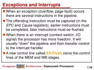
The ‘fetch-execute’ cycle Normal programming assumes this ‘cycle’: • 1) Fetch the next instruction from ram • 2) Interpret the instruction just fetched • 3) Execute this instruction as decoded • 4) Advance the cpu instruction-pointer • 5) Go back to step 1
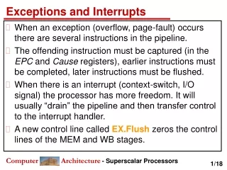
But ‘departures’ may occur • Circumstances may arise under which it would not be appropriate for the CPU to just proceed with this fetch-execute cycle • Examples: • An ‘external device’ might ask for service • An interpreted instruction could be ‘illegal’ • An instruction ‘trap’ may have been set
Faults • If the cpu detects that an instruction it has just decoded would be illegal to execute, it cannot proceed with the fetch-execute cycle • This type of situation is known as a ‘fault’ • It is detected BEFORE incrementing the IP • The cpu will react by: 1) saving some info on its stack, then 2) switching control to a special fault-handling routine
Fault-Handling • The causes of ‘faults’ often can be ‘fixed’ • A few examples: • 1) Writing to a ‘read-only’ segment • 2) Reading from a ‘not present’ segment • 3) Executing an out-of-bounds instruction • 4) Executing a ‘privileged’ instruction • If a ‘problem’ can be remedied, then the CPU can just resume its execution-cycle
Traps • A CPU might have been programmed to automatically switch control to a ‘debugger’ program after it has executed an instruction • That type of situation is known as a ‘trap’ • It is activated AFTER incrementing the IP • It is accomplished by setting the TF flag • Just as with faults, the cpu will react: save return-info, + jump to trap-handler
Faults versus Traps Both ‘faults’ and ‘traps’ occur at points within a computer program which are ‘predictable’ (i.e., triggered by pre-planned instructions), so they are ‘in sync’ with the program (and thus are called ‘synchronous’ interruptions in the normal fetch-execute cycle) The cpu responds in a similar way to faults and to traps – yet what gets saved differs!
Faults vs Traps (continued) • With a ‘fault’: the saved address is for the instruction which triggered the fault – so it will be that instruction which gets re-fetched after the cause of the problem has been corrected • With a ‘trap’: the saved address is for the instruction following the one which triggered the trap
Stack’s layout SS ESP EFLAGS CS EIP SS:ESP In case the CPU gets interrupted while it is executing a user application, then the CPU will switch to a new ‘kernel-mode’ stack before saving its current register-values for EFLAGS, CS, and EIP, and in fact will begin by saving on the kernel-mode stack the register-values for SS and ESP which point to the top of user-mode stack (so it can be restored later on)
Synchronous vs Asynchronous • Devices which are ‘external’ to the cpu may undergo certain changes-of-state that the system needs to take notice of • These changes occur independently of what the cpu is doing, and so cannot be predicted from reading a program’s code • They are ‘asynchronous’ to the program, and are known as ‘interrupts’
Interrupt Handling • As with faults and traps, the cpu responds to ‘interrupt’ requests by saving some info on its kernel stack, and then jumping to a special ‘interrupt-handler’ routine designed to take appropriate action for the particular device which caused the interrupt to occur • The ‘entry-point’ to the interrupt-handler is located via the Interrupt Descriptor Table
The ‘Interrupt Controller’ • Special hardware is responsible for telling the CPU when a specific external device wishes to ‘interrupt’ the current program • This hardware is the ‘Interrupt Controller’ • It needs to tell the cpu which one among several devices is the one needing service • It also needs to prioritize multiple requests
Two Interrupt-Controllers Legacy PC Design (for single-processor systems) and during the Power-On Self-Test during the system-restart initialization x86 CPU Real-Time Clock Master PIC (8259) Slave PIC (8259) INTR Keyboard controller Programmable Interval-Timer
Three crucial data-structures • The Global Descriptor Table (GDT) defines the system’s memory-segments and their access-privileges, which the CPU has the duty to enforce • The Interrupt Descriptor Table (IDT) defines entry-points for the various code-routines that will handle all ‘interrupts’ and ‘exceptions’ • The Task-State Segment (TSS) holds the values for registers SS and ESP that will get loaded by the CPU upon entering kernel-mode
How does CPU find GDT/IDT? • Two dedicated registers: GDTR and IDTR • Both have identical 48-bit formats: Segment Base Address Segment Limit 47 16 15 0 Kernel must setup these registers during system startup (set-and-forget) Privileged instructions: LGDT and LIDT used to set these register-values Unprivileged instructions: SGDT and SIDT used for reading register-values
How does CPU find the TSS? • Dedicated system segment-register TR holds a descriptor’s offset into the GDT The kernel must set up the GDT and TSS structures and must load the GDTR and the TR registers GDT TSS TR The CPU knows the layout of fields in the Task-State Segment GDTR
Segment-Descriptor Format 56 39 63 32 Base[31…24] Limit [19..16] Access attributes Base[23…16] Base[ 15 … 0 ] Limit[ 15 ... 0 ] 31 16 15 0 Quadword (64-bits)
Gate-Descriptor Format 63 32 Entrypoint Offset[ 31…16 ] Gate type code (Reserved) Code-segment Selector Entrypoint Offset[ 15…0 ] 0 31 Quadword (64-bits)
Intel-Reserved ID-Numbers • Of the 256 possible interrupt ID-numbers, Intel reserves the first 32 for ‘exceptions’ • Operating systems such as Linux are free to use the remaing 224 available interrupt ID-numbers for their own purposes (e.g., for service-requests from external devices, or for other purposes such as system-calls
Some Intel-defined exceptions • 0: divide-overflow fault • 1: debug traps and faults • 2: non-maskable interrupts • 3: debug breakpoint trap • 4: INTO detected overflow • 5: BOUND range exceeded • 6: Undefined Opcode • 7: Coprocessor Not Available • 8: Double-Fault • 9: (reserved) • 10: Invalid Task-State Segment • 11: Segment-Not-Present fault • 12: Stack fault • 13: General Protection Exception • 14: Page-Fault Exception • 15: (reserved)
Using our ‘dram.c’ driver We can look at the kernel’s GDT/IDT tables • We can find them (using ‘sgdt’ and ‘sidt’) • We can ‘read’ them by using ‘/dev/dram’ A demo-program on our course website: showidt.cpp It prints out the 256 IDT Gate-Descriptors
Advanced Programmable Interrupt Controllers Multiprocessor-systems require enhanced circuitry for signaling of external interrupt-requests
ROM-BIOS • For industry compatibility, Intel created its “Multiprocessor Specification (version 1.4)” • It describes ‘standards’ for PC platforms that are intended to support multiple CPUs • Requirements include two data-structures that must reside in designated locations in the system’s read-only memory (ROM) at physical addresses vendors may choose
MP Floating Pointer • The ‘MP Floating Pointer structure’ is 16 bytes in length, must begin at an address which is divisible by 16, and must start with this recognizable ‘signature’ string: “_MP_” • A program finds the structure by searching the ROM-BIOS area (0xF0000-0xFFFFF) for this special 4-byte string
MP Configuration Table • Immediately after the “_MP_” signature, the MP Floating Pointer structure stores the 32-bit physical-address of a larger variable-length data-structure known as the MP Configuration Table • This table contains entries which describe the system’s processors, buses, and other hardware components, including I/O APIC
Our ‘smpinfo.c’ module • You can view the MP Floating Pointer and MP Configuration Table data-structures in our workstation’s ROM-BIOS memory (in hexadecimal format) by installing this LKM and then using the ‘cat’ command: $ cat /proc/smpinfo • Entries of type ‘2’ tell where the I/O APICs are mapped into CPU’s physical memory
Multiple Logical Processors Multi-CORE CPU CPU 0 CPU 1 I/O APIC LOCAL APIC LOCAL APIC Advanced Programmable Interrupt Controller is needed to perform ‘routing’ of I/O requests from peripherals to CPUs (The legacy PICs are masked when the APICs are enabled)
Two-dozen IRQs • The I/O APIC in our classroom machines supports 24 Interrupt-Request input-lines • Its 24 programmable registers determine how interrupt-signals get routed to CPUs Redirection-table
Redirection Table Entry 63 56 55 48 32 destination extended destination reserved 31 16 15 14 13 12 11 10 9 8 7 0 reserved M A S K E / L R I R R H / L S T A T U S L / P delivery mode interrupt vector 000 = Fixed 001 = Lowest Priority 010 = SMI 011 = (reserved) 100 = NMI 101 = INIT 110 = (reserved) 111 = ExtINT Trigger-Mode (1=Edge-triggered, 0=Level-triggered) Remote IRR (for Level-Triggered only) 0 = Reset when EOI received from Local-APIC 1 = Set when Local-APICs accept Level-Interrupt sent by IO-APIC Interrupt Input-pin Polarity (1=Active-High, 0=Active-Low) Destination-Mode (1=Logical, 0=Physical) Delivery-Status (1=Pending, 0=Idle)
I/O APIC Documentation “Intel I/O Controller Hub (ICH6) Family Datasheet” available online at http://www.intel.com/design/chipsets/datashts/301473.htm (see Section 10.5)
Our ‘ioapic.c’ kernel-module • This Linux module creates a pseudo-file (named ‘/proc/ioapic’) which lets users view the current contents of the I/O APIC Redirection-Table registers • You can compile and install this module for our classroom and CS Lab machines
In-class exercise #1 • The keyboard’s interrupt is ‘routed’ by the I/O-APIC Redirection Table’s second entry (i.e., entry number 1) • Can you determine its interrupt ID-number on our Linux systems? • HINT: Use our ‘ioapic.c’ kernel-module
In-class exercise #2 • Can you determine how many ‘buses’ are present in our classroom’s machines? • HINT: Use our ‘smpinfo.c’ kernel module and the fact that each bus is described by an entry of type 1 in the MP Configuration Table