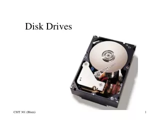
Disk Drives
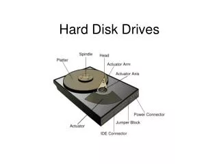
Disk Drives. Geometry Review. A platter is divided into concentric circles called tracks . The tracks are further divided into arcs called sectors . A sector holds 512 bytes of data. There may be additional bytes for servo information.

Disk Drives
E N D
Presentation Transcript
Geometry Review • A platter is divided into concentric circles called tracks. • The tracks are further divided into arcs called sectors. • A sector holds 512 bytes of data. • There may be additional bytes for servo information. • There may be additional bytes for error detection and correction. • In zoned bit recording (ZBR) outer tracks have more sectors than inner tracks.
Data transfer rate is track dependent • The spindle rotates at a specified angular speed (e.g. 7200 RPM). • The data transfer rate depends on this speed. • But since there are more sectors and thus more data at larger radii, the data transfer rate can be track dependent.
Interleaving • When storing a file larger than a sector, it is sometimes faster to store it on non-consecutive sectors • In one-to-one interleaving, the sectors are placed consecutively around a track. • In two-to-one interleaving, every other sector is written to • …
Interleaving (cont.) • The purpose of interleaving is to make the disk drive more efficient. The disk drive can access only one sector at a time, and the disk is constantly spinning beneath the head. • This means that by the time the drive is ready to access the next sector, the disk may have already spun beyond it. • It depends how fast the controller is. Modern controllers are very fast and 1-to-1 interleaving is the norm.
What’s the delay? • Modern controllers are so fast there is effectively no delay between writing one sector and the next and thus interleaving is not necessary. • But if writing requires switching to a different platter (same cylinder) there is a small delay. • And if the writing requires placing data on more than one track/cylinder, there is a more substantial delay in repositioning the head so as to write to the next track.
Cylinder and Head Skew • The sector numbering is staggered to account for delay. • There is staggering from platter to platter within the cylinder. This is known as head skew. • There is staggering from track to track on a given platter. This is known as cylinder skew.
Cylinder and Head Skewing Staggering on a given platter (cylinder skew) and staggering from platter-to-platter (head skew).
Three-Step Process to Use Hard Disk • To prepare a hard disk for use, there are three steps: • Low-level (or physical) formatting • Partitioning • High-level (or logical) formatting
Low-Level Formatting • For hard drives, low-level formatting is done by the manufacturer. • It establishes the tracks, sectors and so on. • It writes the servo information onto the disk. • Any information on a disk is lost if it is low-level formatted. • There are pseudo-low-level formatting utilities that one can run which effectively write 0’s to all of the sectors and replace bad sectors with spares. • This is distinct from true low-level formatting which establishes the sectors.
Partitioning • Partitioning separates the disk into logical pieces. • The standard motivations for partitioning are: • To have multiple operating systems on the same disk (e.g. a “dual boot system”) • To improve disk efficiency, to minimize “slack” and so on. • To separate system files from user files (from virtual memory).
Drive Letters and Partitions • Drive letters A and B are reserved for floppies. (It was standard for early PCs to have two floppy disk drives.) • The computer begins assigning hard drive partitions drive letters starting with C. • All primary drives are assigned letters first. • Next letters are assigned to logical volumes within the extended partition.
Partitions • A drive must have at least one partition. • A drive can have at most four partitions. • These are known as the primary partitions. • One of these is designated as “active” and under normal circumstances one boots from the active drive. • One can achieve the effect of having more than four partitions on one hard drive by designating one as an extended partition (instead of a primary partition). The extended partition can then be divided into logical partitions or logical volumes.
Primary versus Logical • “Boot-ability”: A primary partition is bootable and can be set as the active partition. • Typical schemes reserve primary partitions to act as potential active partitions. That is, if the space is to be used for non-operating-system files, the space will be set up as a logical volume instead of a primary partition. • Drive Letter Assignment: All primary partitions are assigned drives before any logical partition is assigned a drive letter. • Adding (not replacing) a hard drive can result in a reordering of one’s drives if one has logical partitions.
Control Panel/Administrative Tools/Computer Management/Disk Management
Parts of a Primary Partition • A primary partition will contain some combination of the following three things: • System partition: the files need to start the operating system • Boot partition: the operating system files • General purpose partition: any other files (programs and data)
Master Boot Record • The first thing read from the hard drive when a computer starts is the Master Boot record (MBR). • It is located at cylinder 0, head 0, and sector 1. • The MBR consists of: • Master Partition Table • This table is limited in size and only has information about the primary partitions (not any logical volumes) and which primary partition is active • Master Boot Code • A small program to start the boot process
Volume Boot Sector • Each partition has a volume boot sector (or partition boot sector) which contains information about: • The size of the partition • Volume Boot Code: • The Master Boot Code calls the Volume Boot Code of the active partition. The Volume Boot Code starts loading the operating system. • Location of the File Allocation Table (FAT)
Boot sector virus • The master boot code and the volume boot code are the first software code executed after the BIOS (firmware) has started the computer when it is powered up. • This very low-lying code is susceptible to viruses known as boot sector infectors.
High-level formatting • After one partitions a disk, the next level of preparing it to be used is to high-level (or logical) formatting. • Logical formatting provides • Partition boot sector • System ID byte (identifies partition) • Information for the filesystem • Data on bad sectors • Lose data (maybe)
Chipset • Recall that the chipset divides the motherboard traffic into two main categories based on speed. • The Northbridge (a.k.a. Memory Bridge or Memory Hub or Host Bridge) handles the faster traffic. • The Southbridge (a.k.a. I/O Bridge or I/O Hub) handles the slower traffic.
PCI-X • The PCI bus connects to the Southbridge. • But as devices required more speed than the PCI standard allowed, a faster version, PCI-X (Peripheral Component Interconnect eXtended) was developed by IBM, HP, and Compaq. • Whereas PCI allows up to 532 MB per second, PCI-X allows up to 1.06 GB per second. • PCI-X is backward-compatible, • You can install a PCI-X card in a PCI slot (it will operate at the slower PCI speed).
AGP • Another faster variation on PCI developed specifically for displays is AGP, Accelerated Graphics Port. • Came out in 1997 • It works with the Northbridge instead of the Southbridge. • It has a special slot (usually brown in color) • Various throughputs: 266 MB/s (1X), 533 MB/s (2X); and 1.07 GB/s (4X). • Supports pipelining – transmitting many instructions together instead of one at a time. • Being replaced by PCI Express.
Extended ≠ Express PCI Express • PCI Express, PCI-E or PCIe • Introduced by Intel in 2004. • Built to be fast like AGP (faster actually) but general purpose like PCI. • It has point-to-point rather than a (shared) bus structure. And has full-duplex serial connections called lanes –up to 32 lanes. • In PCIe 1.1 each lane carries 250 MB/s (per direction). • PCIe 2.0 supports 500MB/s and PCIe 3.0 supports 1GB/s PER LANE.
In addition to power, hard-drives will have a data connection — either the older PATA (Parallel Advanced Technology Attachment) or the newer SATA (Serial Advanced Technology Attachment)
System Resources • System Resources are the logical/software way to access various devices. It is a level above the hardware but intimately connected to it – as it helps the processor to locate and interface with the hardware. • Data is transmitted between the processor and devices using various shared communication channels (the buses). Thus an addressing scheme is required to determine where data is coming from or where it is going, which device is seeking the attention of the processor, and so on.
System Resources (Cont.) • I/O Addresses: processor talks to device • IRQ: device tells processor it requires attention • DMA: device interacts with memory without bothering processor • Memory Addresses: portion of memory allocated for device instructions
Resource Conflicts • Addresses must be unique if they are to be used to distinguish various devices. • If two devices claim the same resource, there is said to be a conflict. • Certain well established devices use a set IRQ. • Plug-n-Play (PnP) has eliminated a lot of conflicts since the system assigns its own resources to the devices.
Advanced System Information – Another place to look at resources
I/O addresses • Every PC device has an Input/Output (I/O) Address or port address. • Standard devices have standard I/O addresses. • These I/O addresses and the memory locations they represent are like mail boxes for devices. Data for a device is sent to that devices I/O Address (mailbox). • It is also a way to control devices, certain addresses correspond to specific actions of the device. • This scheme of associating memory locations with devices is known as memory-mapped I/O.