Hard Disk Drives
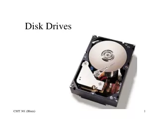
Hard Disk Drives. The Soul of your Computer. Mechanically Speaking. Individual Disks, or Platters Read/Write heads for each platter on actuator arms controlled by servo motor. At arm’s length. Platters are made of aluminum (hence “hard”) with magnetic media on each face.

Hard Disk Drives
E N D
Presentation Transcript
Hard Disk Drives The Soul of your Computer
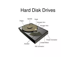
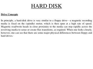
Mechanically Speaking • Individual Disks, or Platters • Read/Write heads for each platter on actuator arms controlled by servo motor
At arm’s length • Platters are made of aluminum (hence “hard”) with magnetic media on each face. • The read/write heads “float,” or fly, above the surface of disk Read/Write head Fingerprint Media Aluminum
Data Encoding • We use “flux reversals” to signal a 1 or 0 • This is serial (one bit at a time)
Encoding Methods • Old methods: • FM. Frequency Modulation. Bit/Timing/Bit • MFM. Modified FM. Timing after two 0’s • Current methods: • RLL. Run Length Limited. Use short patterns to represent longer ones. 1991 • PRML. Partial Response Maximum Likelihood
Even more capacity • Stand the magnets on their nose • Perpendicular recording: • Used in iPod, and starting to appear for us.
Moving the arms • Stepper motors • Moves arm in fixed amounts (angular) • Data transfer errors as motor wears • Thermal expansion errors • Needed to “Park” the heads over non-data area before moving drive • Floppy drives still use stepper motors
Moving the arms • Voice coil “motor” • Same idea as the cone of a speaker
Voice Coil • Don’t need to “Park” the heads – they move automatically when power removed. • No contact means no wear, no thermal issues, faster movement • Can use one disk surface for positioning
Data Storage • Where will we put the data we want to store? • How will we know how to get back to that data the next time we want to use it? • It turns out that three values will get you positioned at a known spot. These three values are called…
Geometry • Every model of drive uses a different geometry – total frustration years ago • Three values used today: Heads, Cylinders and Sectors per track (CHS). • Two obsolete values: write precomp and landing zone
Heads • The number of heads (and thus the number of platters) the drive has installed • Two heads per platter – but a drive may use one head for its own use; thus we can have an even, or odd, number of heads for data use.
Cylinders • Also called “Tracks” • If we hold the heads still for a moment and allow the platters to spin, the heads will describe a circle Track platter Lots of tracks: use concentric circles (same center point, different diameter) Platter !
Sectors per track • Slice each disk like a pie – each part of a track is called a sector • A sector holds 512 Bytes (or less) of data
The other two • Write Precompensation Cylinder. Where the data encoding distance changed • Landing Zone. Where the heads went when parked.
Talk to the drive • IDE. Integrated Device Electronics. Move the controller circuitry to the drive. 1990 Replaced two separate pieces that were joined by two ribbon cables.
Talk to the drive, cont. • SCSI – Small Computer System Interface, that discussion is coming shortly…
IDE/ATA • Started showing up around 1990 • Originally just parallel interface, now called PATA – Parallel AT Attachment Interface • SATA – Serial AT Attachment Interface. Started showing up around 2003
PATA or IDE drives • Western Digital and Compaq in 1989 • Gave it to ANSI for formal specification • Used the AT BIOS routines and two drives up to 504MB (when a 10 MB was huge!) • Enhanced IDE (EIDE) in 1991 • Ultra- DMA in about 1994
Physical Connection • Here is the back of a disk drive: Jumper Block 40-pin connector Pin 1 Power connection
The other end • “Controllers” (really just pin connectors)
Connecting Cable • 40 pins and either 40 wires (Ultra ATA-33) or 80 wires (+40 grounds) for ATA-66,-100 and -133
Setting the Jumper • Because we can connect two drives, we need to distinguish between the two • “Master” and “Slave” – Typically we boot from Master drive, but could boot from Slave drive
Jumper Location • Older drives had jumper location in different places on controller card: Smaller than jumpers on motherboard
Another Drive • Jumper location on back of drive
If I don’t know… • Look around on the drive for jumper block • Read the label • Go to drive manufacturer’s web site for information • Some drives have a “Single” setting that you have to use if only one drive installed
On a 40-wire cable ONLY • Drive to connector is optional:
ATAPI • Advanced Technology Attachment Packet Interface, part of ATA-2 per Michael • Allows CD, DVD and Zip drives to connect to IDE cable(s) and controller • Began at about 24x CD • Scott Mueller says it showed up in ATA-4 • Higher capacities, support for two more devices (total of four)
Translation, ATA-2 • Translates cylinder and head values • We know that 16*2 (32) is the same as 4*8 (32, again), so we fib to CMOS what the “Logical” CHS values are, not the “Physical” values • BIOS uses logical values, controller converts to physical values • Use “extra” bits to allow up to 256 heads
Sector Translation Shift numbers by 16x
ATA-3 • Added S.M.A.R.T. – Self-monitoring, Analysis, and Reporting Technology • In theory, it is to help predict when drive will fail, but it generally is not used
ATA-4 • Introduced Ultra-DMA (does not use the old DMA controller) • Introduced the 80-wire cable (still 40 pins) – optional usage meant no usage • UDMA/33 – 33 MBps max transfer rate • 1996 – 1998 timeframe
LBA • Logical Block Addressing • Divide total number of sectors (C*H*S) to get “new” C, H values leaving S=63 • (1024)(256)(63)(512)=8.4 GB • Both the BIOS and hard disk drive have to be capable of LBA
INT 13h Extensions to LBA • Breaks the 8.4 GB limit • Collect a lot of the bits (plus some previously unused bits) to allow 2^28 address bits • Max drive size moves up to 137 GB • Around 2000
ATA-5 • UDMA/66 – 66 MBps • 80-conductor cable now mandatory else the drive slows down transfer rate; positions on cable are now standardized • 1998 – 2000 timeframe
More on the cable • ATA/66 requires an 80-wire cable. • Contrary to Michael, you CAN use ’66 drive and ’66 controller with 40-wire cable, it just runs slow but no data loss. • Actually, the BIOS will whimper at you at each startup about the cable.
ATA - 6 • UDMA/100 • LBA addressing from 2^24 to 2^48 sectors which breaks 137 GB limit • 2000 – 2002 • Mechanically, we are still at about 60 MBps from read/write head to controller card (on the drive). Add buffer on drive.
ATA - 7 • Introduced SATA drives (-1 and -2; 150 and 300 MBps) • UDMA – 133; never made it to mass production
Drive Maximums • Prior to 1995 – 528 MB • BIOS CHS (1024,16, 63) limit • Prior to Jan 1998 – 8.4 GB • “Logical” heads to 256 (LBA) • Prior to Sept 2002 – 137 GB • Interrupt 13 (Int13) extensions; feed drive stream of addressable sectors Now no limit with 2^48 bits (up from 2^24) but we stop at 2.2TB
SATA • Fewer wires (7) = thinner cable; Differential signals (+ and – voltage) • Up to one meter long cable (from 18”) • Point to point connection – one device per cable so no Master/Slave issue • Performance is issue: 150 MBps vs. IDE at 133; SATA-II at 300 MBps burst mode SATA III at 600MBps • Host Bus Adaptor – where SATA plugs in 20
Data Power
AHCI • Advanced Host Controller Interface • Windows Vista and later • Works with SATA HBA (host bus adapter) • Makes the drive show up in Computer • Enables native command queuing; disk optimization feature
SCSI • Small Computer System Interface • 1970’s by Shugart • Uses a “chain” approach – device to device to Host Adapter/Controller • Can be internal (68-pin) or external (50-pin); newest use 68-pin external • Apple (older) used 25-pin connector (SCSI-1)
SCSI ID • Use a number to identify devices on a link • Can be any number (0-7 for SCSI-1); 0-15 for SCSI-2 or -3 • Host adapter usually set to 7; boot device set to 0
Termination • Easy – both ends of the SCSI chain • Most devices have termination built in; can cause fits getting termination correct • Do it wrong and device(s) won’t show up
Configuring CMOS • At first, we had to know, then type in, the CHS values for a drive – lots of hassle • Today, CMOS will get its information from the drive automatically – even SATA drives
Drive Types • Rather than Cylinders, Heads and Sectors numbers, use Types • We worked our way up to 46 different types, Type 47 was “User Defined” and we were back to CHS values