Download

1 / 103
1.03k likes | 1.25k Vues
HP WL520 Wireless Access Point. Module contents. Product overview New features Installation of the HW Configuration Scantool Using the web-browser Using the CLI Rescue procedures. WL520 What is it?. High performance dual access wireless Access Point and Ethernet MAC Bridge

E N D
HP WL520 Wireless Access Point
Module contents • Product overview • New features • Installation of the HW • Configuration • Scantool • Using the web-browser • Using the CLI • Rescue procedures
WL520 What is it? • High performance dual access wireless Access Point and Ethernet MAC Bridge • Double capacity • Migration to future high speed Wireless LANs • Wireless Bridging (WDS) • H/W: • Intel StrongARM 110 processor (16 MB SDRAM memory, 8MB Flash Memory) • 10BaseT / 100Base-T (UTP) Ethernet • 2 slots for ORiNOCO PC Cards • 8-pin MiniDin serial connector for optional configuration • Powered via Active Ethernet, using splitter (or via PS) • S/W: • Real-Time Operating System (RTOS) built on VxWorks • Supports IEEE802.1x Security • Manageability • Windows-based ORiNOCO manager • Web Browser (http interface) • CLI, via Telnet or local console
TFTP server WL520 Image file Kernel AP Firmware Con- figuration Data BSP/Boot loader TFTP transfer WL520 Flash ROM Original BSP/Boot loader Upgrade BSP/Boot loader ORiNOCO PC Card ORiNOCO PC Card RAM AP Firmware AP Firmware Buffers, Filter & bridge tables Con- figuration Data Kernel AP Firmware Port 1 Port 2 Port 3 RS232 Port Ethernet Interface WL520Functional diagram • The WL520 operates its software from an embedded image (kept in FlashROM, but executed from RAM): • Uploading of image is executed with the help of a TFTP server. • Users can initiate transfer of • Image (kernel and AP firmware) • BSP.Bootloader upgrades • Configuration data (MIB-II) • System leaves factory with only “Original BSP/Bootloader” on board. Cannot be overwritten by users • New bootloader version can be inserted in different area “Upgrade BSP/Bootloader” • When both bootloaders are present, the Upgrade bootloader is active (not the orginal bootloader) • On start of operation, AP Firmware is placed in PC Cards
WL520Functional diagram - Kernel software • Kernel portion of the image contains the heart of the WL520; it includes: • The VxWorks operating system that controls the operation and manages the resources • The devices drivers such as the ORiNOCO PC Card driver and the the Ethernet driver • IEEE 802.1x support • The actual bridging software, that implements the filtering and forwarding of frames • The IP stack to allow the devices to be managed from other network locations • The UDP protocol to support IAPP and SNMP • The TCP protocol to support Telnet • The Radius Client to allow Radius MAC based authentication • The IAPP protocol to support roaming • The SNMP agent for configuration & management • DHCP Client to dynamically obtain IP addresses Kernel Radius client IAPP TFTP SNMP agent Telnet VxWorks Kernel DHCP client/server UDP TCP IP ICMP IEEE802.1x security 802.3d Bridging SW ORiNOCO PC Card driver 802.3 Ethernet driver Other device drivers
Module contents • Product overview • New features • Installation of the HW • Configuration • Scantool • Using the web-browser • Using the CLI • Rescue procedures
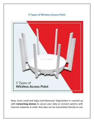
New Features • Dual band device (5 GHz support) • VLAN • Auto Channel Select • Ultra high density • WEP Key rotation • Changed GUIs for configuration and management
New Features5 GHz kit • Upgrade kit to add dual mode capability to WL520 (field upgradeable) • Supports 802.11a clients, when adapter is inserted in WL520 CardBus slot • Integrated assembly of CardBUS 802.11a radio adapter and diversity antenna system • 5GHz radio based on Atheros reference design • Antenna system fitted with Rabbit ears to allow proper vertical positioning independent of position of the AP • Antenna assembly designed to fit snugly in place on WL520 mounting bracket • Adapter needs to be inserted in PC Card slot A (left slot when facing the WL520)
New Features5 GHz kit - HW Characteristics • Orthogonal Frequency Division Multiplexing (OFDM) modulation • each “channel” composed out of 52 sub-carriers of which 48 can carry information • 64 QAM, 16 QAM, QPSK, BPSK • Data rates • 54, 48, 36, 24, 18, 12, 6 Mbit/s; auto fall back • Media Access Protocol • CSMA/CA with ACK • Frequency bands • FCC U-NII (8 Channels) • 5150-5350 MHz (5.18, 5.2, 5.22, 5.24, 5.26, 5.28, 5.3, 5.32 GHz) • TELEC--Japan (4 Channels) • 5170, 5190, 5210, 5230 MHz • Output power • 17 dBm
1 2 4 3 5 Installation of the 5 GHz kit 1. With the WL520 processor module mounted on the mounting bracket, position the 5 GHz antenna adapter, card inward, facing the top of the WL520 unit and insert the PC card into slot A. 2. Angle the antenna adapter slightly upwards, pinch the end tabs inwards and carefully slide the antenna adapter onto the mounting bracket. 3. Snap the center tabs under the WL520 processor module. 4. Gently push forward while rotating the antenna downwards and clip the adapter into the small cutouts on the face of the mounting bracket. 5. Position the antenna for best reception: — at a 90 o angle for flat surface mounts — at a 180 o angle for wall mounts
New FeaturesWL520 with GHz kit - key aspects • Dual mode infrastructure • The WL520 with the new 5GHz kit added, can simultaneously support new 802.11a (5GHz 54 Mbit/s) as well as existing 802.11b (2.4GHz 11 Mbit/s Wi-Fi) client stations • Higher data rate and more capacity • The new 5GHz technology enables higher data rates for faster response times and the ability to run more “bandwidth hungry” applications, as well as more capacity (channels) allowing more users on the network in one area • Extended range 802.11a • Special external antennae provide 25% more range than some other products in the market using integrated antennae • Migration path for investment protection • The 802.11a WL520 5GHz kit offers a cost effective migration path to upgrade WLAN infrastructure rather than replacing complete access points
New FeaturesACS – Automatic Channel Select • Active Scan for 802.11b • Active Scan for FCC 802.11a • Passive scan for ETSI 802.11a • Automatic Channel Selection based on: • Regulatory Domain (FCC, ETSI, etc.) • Channel signal and noise measurements • Adjacent channel noise • Minimizes need for Site Survey • Reduces Setup Time • Feature available for both 802.11a and 802.11b cards • Best channel to select is one with lowest SNR (on both ends of the link)
New FeaturesAP List • Proprietary Feature Supported by Site Monitor Function of the Client Manager Utility • Resolves AP Name (sysName) to MAC Address • Displays both AP Name (sysName) and MAC Address for Access Points in multicast group • Simplifies identification and management of many Access Points
New FeaturesVLAN Management VLAN for Enhanced Management Access Control • Supports two (2) user VLANs and one (1) management VLAN • One (1) VLAN per Wireless NIC • VLAN assignment based on Network Name • User VLAN • Interoperable with all security modes: • WEP, 802.1x, Mixed Mode (802.1x and WEP) • Segments Wireless LAN • Provides control of wireless user access to wired LAN • Support for insertion/removal of 802.1Q compliant VLAN identifiers or tags (1 to 4094) • VLAN identifiers configurable via management interfaces (CLI, Web, and SNMP) • Support for mixed environment (both VLAN aware and Non-VLAN aware devices) • Management VLAN • Provides Enhanced control of management access to AP • Management Station must be on the Management VLAN to manage AP 2 User VLANs Segmented on Wireless LAN side of Network Using Network Names (1 VLAN segment per Wireless NIC)
Module contents • Product overview • New features • Installation of the HW • Configuration • Scantool • Using the web-browser • Using the CLI • Rescue procedures
WL520Kit Contents • Mounting plate to mount the WL520 unit to a wall • Mounting plate is ready to hold standard Power Supply or optional Active Ethernet Splitter (splits UTP input in Ethernet data, and DC Power) • Power Supply • WL520 Processor Module • Cover • ‘Getting Started’ user guide • CD-ROM containing software and documentation • Accessories for mounting the unit • AC Power Cord • MiniDin 8-pin to DB-9 adapter
1 2 3 4 5 Installation of the WL520How to set it up? 1. Clip power supply unit (or power splitter when using Active Ethernet) to the mounting plate 2. Slide the processor module onto the mounting plate 3. Insert one or two ORiNOCO PC cards 4. Optionally attach the range extending antenna and connect the Ethernet cable 5. Attach the plastic cover plate and click it into position
1 3 2 10 4 7 8 9 5 6 Installation of the WL520Processor module 1. 10/100BaseT Ethernet port (RJ45) 2. Serial connector (MiniDin 8-pin) 3. Power connector 4. Reset switch • To reboot and restart the WL520 5. Reload switch • Used during emergency reset procedure (re-setting the parameters to factory default values) 6. Power LED 7. Ethernet traffic LED 8. Traffic LED (ORiNOCO PC-Card A) 9. Traffic LED (ORiNOCO PC Card B) 10. Serial Number label
Power Ethernet Wireless A Wireless B Installation of the WL520 Physical Indicators (LEDs on the WL520) • Run time, the LEDs show (from left to right): • Power Green - Power enabled • Ethernet flicker Green - Ethernet LAN activity • Wireless A Green - Wireless LAN activity on slot A • Wireless B Green - Wireless LAN activity on slot B • Error conditions: • During boot sequence all LEDs (except for the Ethernet LED) will be solid amber • When boot-sequence cannot be completed all LEDs will flash red • After boot-sequence completion and failure to initialize, the Power LED will maintain amber • When ORiNOCO PC card is present but malfunctioning its associated LED will stay red
Module contents • Product overview • New features • Installation of the HW • Configuration • Scantool • Using the web-browser • Using the CLI • Rescue procedures
Configuration and ManagementOut of box Defaults (WL520) • WL520 Identifiers: • IP Address: 10.0.0.1 • IP Address type: Dynamic • Sub-net mask: 255.0.0.0 • Tftp server address: 10.0.0.2 • Tftp filename: FILENAME • Password: public • Read/Write password: public • Wireless Interfaces • RF Channel: Default setting of Wireless PC Cards • Network name: My Wireless Network A, My Wireless Network B • Encryption: Disabled • RTS/CTS (Medium Reservation): Disabled • Multicast-rate: Auto select 1-2 Mbps
Configuration and ManagementConfiguration tools • To configure the WL520 the following tools can be applied: • Using standard browser and built-in http-interface • Using the AP Scan tool (for initial basic settings) • Command Line Interface (CLI): • Using Telnet • Using terminal emulation via serial port • Using the Windows-based ORiNOCO Manager WL520 Unit to be configured Configuration device
WL520 Unit to be configured Ethernet Ethernet Cross-over cable Hub Ethernet IP Networks Configuration device Configuration and ManagementConfiguration tools - Using the http-interface Configuring WL520 via web-browser • Local connection using • Wireless connection • Ethernet Cross-over cable • two Ethernet patch cords and a hub • Using an IP network (remote connection) • When both devices are on the same segment, the IP addresses need to be in the same sub-net • When routers are available (as in an IP network), the IP address of the WL520 need to be known • Starting the browser with the IP address of the WL520 will trigger the configuration tool
WL520 Unit to be configured Ethernet Ethernet Cross-over cable Hub Ethernet Configuration device Configuration and ManagementConfiguration tools - Using the AP scan tool Using the AP Scan Tool • Windows based tool • Scans the local segment for WL520 devices (does not pass router) • Displays WL520 with their IP addresses (needed for subsequent configuration using the web browser) • Allows for limited initial configuration: • IP address • Sub-net mask • Read/Write Password • System name • IP address of both devices need to be in the same sub-net
Module contents • Product overview • New features • Installation of the HW • Configuration • Scantool • Using the web-browser • Using the CLI • Rescue procedures
AP Scan ToolInitial settings • Using the web-browser requires knowledge of the IP address of the AP • The scan tool will show locally discovered WL520 systems showing: • IP address • MAC address • AP name • Uptime • System description (incl. The version level of the image)
AP Scan ToolInitial settings • Using the “Change” button limited configuration changes can be made: • Setting the AP for use of static IP address or obtaining from DHCP server • When selecting static setting: • IP address • Sub net mask • IP address of default gateway • When changes are made the user can needs to enter the read/write password
Module contents • Product overview • New features • Installation of the HW • Configuration • Scantool • Using the web-browser • Using the CLI • Rescue procedures
Configuration via web-browserStatus screen • “Help” button has moved from to left hand side of GUI (Question mark icon has been removed) • “Exit” button has been added • “Contact Name” and “Contact email” added to general information section • Additional comment line added to introduce the traps/alarms list
Configuration via web-browserConfiguration start screen • Extra (generic) screen has been added with links to various configuration sub-screens (in addition to the tabs)
Configuration via web-browserConfiguration - System parameters • The Inventory data (version levels of installed elements) has been moved from the “System” Configuration screen to the “monitor” section. • The “System” tab allows changes for: • (Device) Name • (Device) location • Contact person’s name • Contact person’s email address • Contact person’s phone #
Configuration via web-browserConfiguration - Network - IP Configuration • The “Network” tab now consists of 4 sub-tabs to configure the network characteristics of the WL520 (VLAN has been added) • IP Configuration settings; • “Static” or “Dynamic”; • Static = preset IP Address • Dynamic = IP address assigned by DHCP server • In case of Static IP address the following fields are to be entered: • IP Address • Sub-net mask • IP address of default router • Default value for Time to Live
Configuration via web-browserConfiguration - Network - DHCP server • The WL520 can also act as DHCP server, issuing IP addresses to clients • The “DHCP Server” tab allows setup of this function: • Enabling or disabling the server • Identifying optional IP addresses for a DNS server that the clients could use • Identifying the IP address of a default router that the clients could use • IP Pool table entries include • The lease time of the IP address (default and maximum)
Configuration via web-browserConfiguration - Network - DHCP server • To complete the DHCP Server setup, one or more IP pools have to be created. • Clicking “Add” allows for adding an IP pool by providing a start- and end- address
Configuration via web-browserConfiguration - Network - DHCP server • To complete the DHCP Server setup, one or more IP pools have to be created. • Clicking “Add” allows for adding an IP pool by providing a start- and end- address • IP Pool table entries include • The lease time of the IP address (default and maximum) • When the pool has been added, the user is returned to DHCP server screen, which will show the entered pool
Configuration via web-browserConfiguration - Network - Link Integrity • Link integrity allows the AP to check its connection to the backbone by periodically ping up to 5 different IP locations • When none of the identified correspondents reply, the WL520 considers its backbone lost, and will disassociate its connected devices • This tab allows the user to identify these 5 addresses
Configuration via web-browserConfiguration - Network - Link Integrity • Link integrity allows the AP to check its connection to the backbone by periodically ping up to 5 different IP locations • When none of the identified correspondents reply, the WL520 considers its backbone lost, and will disassociate its connected devices • This tab allows the user to identify these 5 addresses • By clicking “Edit”, the window is displayed that allows entry of target IP addresses used in the link integrity function
Configuration via web-browserConfiguration - Interfaces - Wireless • The “Interfaces” tab allows entering settings for available communication interfaces: • Wired (Ethernet) interface • 2 Wireless interfaces (one for each PC Card slot) • The screen displayed depends on the wireless PC card inserted (WiFi or 5GHz) • For 5 GHz devices, less parameters are configurable than for 2.4 GHz cards • Parameters to set on the wireless interface include: • Network name (SSID) • Auto Channel Select toggle • Medium Reservation • DTIM period
Configuration via web-browserConfiguration - Interfaces - Wireless • Parameters to set on the wireless interface include (cont’d): • Frequency channel by lowering the drop-down list and selecting a value from the list
Configuration via web-browserConfiguration - Interfaces - Wireless • Parameters to set on the wireless interface include (cont’d): • Transmit rate by lowering the drop-down list and selecting a value from the list • Items not supported on 5 GHz radios: • WDS • Distance between APs • Closed System toggle • Load balancing toggle • Medium density distribution toggle • Interference robustness toggle
Configuration via web-browserConfiguration - Interfaces - Wireless • For 2.4 GHz devices, following parameters are configurable: • Network name (SSID) • Auto channel select • DTIM period • Medium reservation • Interference robustness • Closed system • Load balancing • Medium density distribution
Configuration via web-browserConfiguration - Interfaces - Wireless • For 2.4 GHz devices, following parameters are configurable (cont’d): • Frequency channel by lowering the drop-down list and selecting a value from the list
Configuration via web-browserConfiguration - Interfaces - Wireless • For 2.4 GHz devices, following parameters are configurable (cont’d): • Distance between AP’s by lowering the drop-down list and selecting a value from the list
Configuration via web-browserConfiguration - Interfaces - Wireless • For 2.4 GHz devices, following parameters are configurable (cont’d): • Multicast rate by lowering the drop-down list and selecting a value from the list
Configuration via web-browserConfiguration - Interfaces - Wireless • Wireless Bridging can be enabled by setting up WDS (Wireless Distribution System) • Clicking “Edit” allows for entry of up to 6 WDS links
Configuration via web-browserConfiguration - Interfaces - Wireless • Wireless Bridging can be enabled by setting up WDS (Wireless Distribution System) • Clicking “Edit” allows for entry of up to 6 WDS links • On each link the MAC address of the ORiNOCO PC Card, on the other end of the WDS link, has to be entered • Setting this address has to be done on both ends (in both WL520 systems) • It is not needed for both ends of a WDS link to have the same Port-index number
Configuration via web-browserConfiguration - Interfaces - Wireless • Wireless Bridging can create complicated topologies and need to be carefully used • Multiple Hop links • Chain of APs • Extend the distance to be covered • May lead to long end-to-end latency figures (needs to match the application requirements) • Circular link • Can create IP loops leading to decrease in performance • Can be used to create back-up paths • Needs Spanning tree to be set • WDS links need to be set to same frequency channel • Can also be same PC card that also drives a cell, but could be 2nd PC Card in AP • Reduces performance
Configuration via web-browserConfiguration - Interfaces - Ethernet • On the Ethernet Interface a selection can be made from a drop-list to match the attached media: • 10 Mbps, Half-duplex • 10 Mbps, Full-duplex • 10 Mbps, Auto-duplex • 100 Mbps, Half-duplex • 100 Mbps, Full-duplex • Auto-speed, Half-duplex • Auto-speed, Auto-duplex
Configuration via web-browserConfiguration - Management - Passwords • The WL520 can be configured via: • SNMP tools • Telnet • Web browser • For each method protection can be established thru passwords