Download
1 / 25
250 likes | 292 Vues
This project aims to create a lab-scale test to assess the flammability of non-traditional aircraft fuselage materials, crucial for future certification. It involves testing various composite materials with different levels of flame retardants to ensure safety standards equivalent to aluminum.

E N D
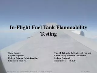
Development of In-Flight Flammability Test for Composite Fuselage Aircraft
Outline • Introduction • Objective • Test Plan • Radiant Heat Transfer • Summary
Introduction • Modern commercial aircraft are being designed with increased amounts of composite materials in the aircraft fuselage and structures • Composite resins can have a very wide range of flammability • Traditional aircraft fuselage and structures are constructed from aluminum, which does not react when exposed to a hidden fire source in flight • It must be proven that if an aircraft is to be constructed of non-traditional materials, the materials chosen must provide at least an equivalent level of safety to aluminum • Intermediate scale tests have been used to date to show equivalency, but a lab scale test with well defined criteria is necessary for future certification purposes
Objective • Develop a lab-scale test to determine the propensity of a non-traditional fuselage material to propagate a flame or to sustain flaming combustion • Test criteria is to be based upon intermediate scale testing • Standard fire source used to simulate a hidden fire • 4” x 4” x 9” untreated urethane foam block • 10cc of heptane soaked into foam to provide more uniform burning • Various materials of similar mass and rigidity will be tested, both aircraft grade and non-aircraft
Laminate Structural Plies Honeycomb Core Structural Plies Flame Propagation % additives Materials to Test • Fiber-reinforced polymer composites • Carbon-epoxy • Unidirectional and woven carbon fiber layups • Variations of resin systems • From most flammable to least flammable • Create a sample set of materials with a particularly flammable resin system • Dope some samples with various amount of flame retardants • Brominated epoxies to effect gas phase (high smoke/low char) • Phosphorous compounds to effect condensed phase (low smoke/high char) • Flammability “should” directly link to percentage of flame retardant compounds mixed in the resin system • Sandwich panels • Structural plies bonded to honeycomb cores
Test ConfigurationIntermediate Scale • Panel Construction • 18” x 48”, varying thicknesses 1/8” and up • Solid laminates • Thin laminates (<10 plies) sandwiching honeycomb core • Panel at 45° angle to foam block • Flat panels only, no curvature • No structural members • Fire source – untreated urethane foam block, 4” x 4” x 9”
Intermediate Scale Lab Scale = ?
Test ConfigurationLab Scale • Use identical materials from intermediate scale • Sample size 12” x 24” • Use radiant panel apparatus for lab scale testing • Develop test parameters based on intermediate scale results • Calibration heat flux • Pre-heat • Flame impingement time
Radiant Heat Transfer • Emissivity, thermal conductivity of sample materials will dictate surface temperature • Surface temperature directly relates to the volatilization of material components and therefore the flammability of the material • For a standard incident radiant heat flux, different materials will attain varying surface temperatures • A preheat time should be determined that can bring most materials to a particular surface temperature range Incident radiant heat Reflected heat Net heat transferred to surface εsurface Sample Material Resultant absorbed heat – Conducts through material
1.5” Sample 1.5”
Heater Sample Holder Heater Sample Holder • Heater calibrated to 2.2 BTU/ft2s • Sample exposed for 15 min • Sample allowed to cool for 15 min Front View Rear View
Painted Composite Samples – Before Silver Gray White Front T/C Three composite samples, 1/8” thick, 1.5” x 1.5”, painted with high temp spray paint Thermocouple on front surface (shielded from radiant heat) and on center of back surface Kaowool insulation around and behind the sample
After White Gray Silver Silver sample exhibited no delamination or smoking Gray and White samples exhibited smoking, delamintation, and swelling
Observations • Surface color determines the amount of radiant heat absorbed by material • Shiny surfaces reflect more radiant heat than darker surfaces • For this carbon/epoxy material exposed to a radiant heat flux, the surface color determines the amount of time it takes for the surface temperature to reach the onset of vaporization • Determine if this has an effect on flame propagation in both intermediate scale and lab scale
Summary • Intermediate scale testing will begin with non-aircraft materials • Plywood • Acrylic • Honeycomb panels • Fiberglass • Custom formulated composites will be ordered • Effect of surface color on flame propagation will be studied
Composites Task Group – Thursday A.M. • Discuss approach to intermediate scale flame propagation • Materials • Lab scale test parameters
Contact: Robert Ochs DOT/FAA Tech Center BLDG 287 Atlantic City Int’l Airport NJ 08405 robert.ochs@faa.gov 1 (609) 485 4651