Electron Cloud Effects in Accelerators
This workshop is dedicated to the memory of Francesco Ruggiero and focuses on the electron cloud effect in accelerators. The workshop will cover topics such as the history, simulations, recent observations, and mitigation strategies of the electron cloud effect.

Electron Cloud Effects in Accelerators
E N D
Presentation Transcript
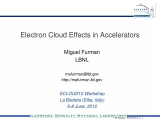
Electron Cloud Effects in Accelerators Miguel Furman LBNL mafurman@lbl.gov http://mafurman.lbl.gov ECLOUD12 Workshop La Biodola (Elba, Italy) 5-8 June, 2012
Francesco Ruggiero, 1957-2007 This workshop is dedicated to the memory of Francesco Ruggiero. I met Francesco on many occasions during my career. I feel honored to have met him and grateful for what I learned from him. I am indebted for his strong support of electron-cloud R&D at CERN and elsewhere.
Summary • What is the electron-cloud effect (ECE) • Primary and secondary electrons • Brief history • Simulations • Recent observations • Mitigation • Conclusions Acknowledgments: I am grateful for collaboration and discussions over time with: A. Adelmann, G. Arduini, V. Baglin, S. Berg, M. Blaskiewicz, O. Brüning, Y. H. Cai, J. Calvey, F. Caspers, C. Celata, R. Cimino, R. Cohen, I. Collins, J. Crittenden, F.-J. Decker, G. Dugan, N. Eddy, A. Friedman, O. Gröbner, K. Harkay, S. Heifets, N. Hilleret, U. Iriso, J. M. Jiménez, R. Kirby, I. Kourbanis, G. Lambertson, R. Macek, A. Molvik, K. Ohmi, M. Palmer, S. Peggs, G. Penn, M. Pivi, C. Prior, A. Rossi, F. Ruggiero, G. Rumolo, D. Sagan, K. Sonnad, D. Schulte, P. Stoltz, J.-L. Vay, M. Venturini, L. Wang, S. Y. Zhang, X. Zhang, A. Zholents, F. Zimmermann, R. Zwaska,…
What is the ECE(illustrated with the LHC cartoon by F. Ruggiero) • Beam emits synchrotron radiation: • provides source of photo-electrons • other sources: beam-gas ionization, stray protons striking the wall • Photo-electrons get rattled around the chamber from multibunch passages • especially for intense positively-charged beams (e+, protons, heavy ions) • Photoelectrons yield secondary electrons • yield is determined by the secondary emission yield (SEY) function δ(E): • characterized by peak value δmax at E=Emax • e– reflectivity δ(0): determines survival time of e– • Typically, δmax~1–3, and Emax~200-400 eV • Typical e– densities: ne=1010–1012 m–3 (~a few nC/m) • Typical e– energies: <~ 200 eV’s (with significant fluctuations)
EC formation: beam-induced multipacting (BIM) • train of short bunches, each of charge Qb=NbZe, separated by sb • Dt = e– chamber traversal time • b = chamber radius (or half-height if rectangular) The parameter defines 3 regimes: (Dt = e– chamber traversal time) If G = 1 and deff > 1, EC can grow dramatically (O. Gröbner, ISR; 1977)
Consequences • Possible consequences: • single-bunch instability • multibunch instability • emittance growth • gas desorption from chamber walls • excessive energy deposition on the chamber walls (important for superconducting machines, eg. LHC) • particle losses, interference with diagnostics,… • In summary: the ECE is a consequence of the interplay between the beam and the vacuum chamber “rich physics” • many possible ingredients: bunch intensity, bunch shape, beam loss rate, fill pattern, photoelectric yield, photon reflectivity, SEY, vacuum pressure, vacuum chamber size and geometry, … • The ECE is closely related to the mechanism of photo-amplifiers * IT IS ALWAYS UNDESIRABLE IN PARTICLE ACCELERATORS * IT IS A USUALLY A PERFORMANCE-LIMITING PROBLEM * IT IS CHALLENGING TO PROPERLY QUANTIFY, PREDICT AND EXTRAPOLATE
Importance of the EC • ECE has been observed at many p or e+ storage rings: • PEP-II, KEKB, BEPC, PS, SPS, LHC, APS, RHIC, Tevatron, MI, SNS, CESRTA … • Actual or potential diminished performance • and/or • Dedicated experiments • PEP-II and KEKB: • controlling the EC was essential to achieve and exceed luminosity goals • PEP-II antechamber lets ~99% of photons escape; the remaining 1% seeds the EC via SEE • TiN coating at PEP-II: suppresses SEY, but was not enough • Solenoidal B-fields, B~20 G (at both machines) trap electrons near chamber surface • Complicated beam fill patterns were used for a while • PSR: high-current instability, beam loss • Decision to coat SNS vacuum chamber with TiN • RHIC: fast vacuum pressure rise instability at high current forced beam dump (in some fill patterns) • problem was severe at transition energy (very short bunch length) • not any more (TiZrV coatings suppress SEY) • Concern for future machines (LHC upgrade, ILC DR’s, MI upgrade,…)
Brief history: BCE and CE • BCE: effect first seen many years ago in proton storage rings: • two-stream instabilities (in space-charge compensated coasting beams) • BINP, mid 60’s: G. I. Budker, V. G. Dudnikov, … • ISR, early 70’s: E. Keil, B. Zotter, H. G. Hereward,… • Bevatron (LBL), early 70’s: H. Grunder, G. Lambertson… • beam-induced multipacting (ISR, mid 70’s, bunched beams) • O. Gröbner, ICHEA 1977 • multibunch effect; pressure rise instability • High-intensity instability at PSR (LANL), since mid 80’s • single-long-bunch effect • Fairly conclusively identified as an electron effect in 1991 (D. Neuffer, E. Colton, R. Macek et al.) • CE: started in early 90’s, KEK Photon Factory: • M. Izawa, Y. Sato and T. Toyomasu, PRL 74, 5044 (1995) • First observation of instability sensitivity to beam-charge sign in a lepton ring • Electrons in the chamber were immediately suspected (assumption: from ionized gas) • Quick decision to add an antechamber to the PEP-II e+ ring chamber • first simulations: K. Ohmi, PRL 75, 1526 (1995); “photoelectron instability” (PEI) • First time photoelectrons were suspected • F. Ruggiero, 1997: start LHC ecloud “crash programme”
ECLOUD and related workshops CEIBA95: Intl. Workshop on Collective Effects and Impedance for B Factories (KEK, June 1995) Santa Fe 1997: Workshop on Electron Effects in High-Current Proton Rings (Santa Fe, March 1997) MBI97: Intl. Workshop on Multibunch Instabilities in Future Electron and Positron Accelerators (KEK, July 1997) Santa Fe 2000: 8th Advanced Beam Dynamics ICFA Mini-Workshop on Two-Stream Instabilities in Particle Accelerators and Storage Rings (Santa Fe, Feb. 2000) Two-Stream’01: Intl. wkshp. on two-stream instabilities in part. accelerators & storage rings (KEK, Sept. 2001) ECLOUD’02: Mini-Workshop on Electron-Cloud Simulations for Proton and Positron Beams (CERN, Apr. 2002) Mini-Workshop on SPS Scrubbing Run Results and Implications for the LHC (CERN, June 2002) Pressure Rise’03: 13th ICFA beam dynamics mini-wkshp. on beam-induced pressure rise in rings (BNL, Dec. 2003) ECLOUD’04: 31st ICFA Advanced Beam Dynamics Workshop on Electron-Cloud Effects (Napa, April 2004) ECL2: Joint CARE-HHH, CARE-ELAN and EuroTeV mini-wksp. on electron-cloud clearing (CERN, Mar. 2007) ECLOUD’07: Intl. Workshop on Electron-Cloud Effects (Daegu, April 2007) ECM’08: CARE-HHH-APD mini-workshop on electron-cloud mitigation (CERN, Nov. 2008) AEC’09: EuCARD-AccNet-EuroLumi wkshp. on anti e-cloud coatings that require no activation (CERN, Oct. 2009) ECLOUD’10: 49th ICFA Advanced Beam Dynamics Workshop on Electron Cloud Physics (Cornell U. Oct., 2010) EuCARD-AccNet CERN-GSI mini-wkshp. on modeling electron-cloud effects (CERN, March 2011)
Simulations of the ECE • Four main physics components: • Photon emission from beam and photon propagation • Photoelectron emission and electron propagation • Secondary electron emission and electron propagation • Effects of the ecloud on the beam • Three basic kinds of codes in use: • Photon emission and tracking (SYNRAD3D, Cornell U.; G. Dugan’s talk) • (early code PHOTON (F. Zimmermann, LHCPR-237, Oct. 2000) was applied to the LHC) • Build-up codes: simulate the development of the EC by the action of a given, prescribed beam (ECLOUD, POSINST, PEI,...) • Beam dynamics codes: simulate the dynamics of the beam by the action of a given initial ecloud density (WARP, VORPAL, CMAD, CLOUDLAND, PEHTS, HEADTAIL, QUICKPIC...) • Code repo: http://care-hhh.web.cern.ch/CARE-HHH/simulation_codes_catalogue_and_repository.htm • LHC ecloud database: http://ab-abp-rlc.web.cern.ch/ab-abp-rlc-ecloud/ New!
Example: beam+ecloud self-consistent simulation: SPS at injection • J.-L. Vay, IPAC12-WEPPP076 • Code WARP+POSINST: 3D, parallel, multibunch, with feedback • SPS at E=26 GeV (injection) • Nb=1.1e11 • 3 batches of 72 bunches each (tb=25 ns, tbatch=200 ns) • includes SEY model from POSINST (dmax=1.18) • Bunch-to-bunch feedback (g=0.1) in horizontal plane (no V feedback) • Ecloud was reinitialized to 0 at the beginning of every turn • Seed mechanism: ionization of residual gas • But proton density was allowed to evolve continuously for the 1000 turns • Full run was for 1000 turns • 9,600 CPUs on Franklin supercomputer (NERSC) 11
Simulation parameters for SPS at injection, tb=25 ns • Bunch • energy W=26. GeV • population Np=1.11011 • RMS length z=0.23 m (Gaussian profile) • momentum spread p/p=210-3 • transverse normalized emittance x= y=2.8 mm.mrad • longitudinal normalized emittance z=0.3 eV.s • : continuous focusing • beta functions x,y= 33.85, 71.87 • betatron tunes x,y= 26.13, 26.185 • chrom. Qx,y=0.,0. • // : continuous focusing • momentum compaction factor =1.9210-3 • cavity voltage V = 2 MV • cavity harmonic number h = 4620. • assumed 100% dipole • Bunch-to-bunch feedback system in horizontal plane (gain=0.1) • 10 interaction stations/turns 12
Warp and Posinst have been further integrated, enabling fully self-consistent simulation of e-cloud effects: build-up & beam dynamics Turn 1 CERN SPS at injection (26 GeV) Turn 500 13
Bunch and ecloud evolution at a fixed location(3 batches of 72 bunches, 1 movie frame every 25 ns) NOTE: one movie frame every 25 ns
Bunch and ecloud evolution at a fixed location(3 batches of 72 bunches, 1 movie frame every 25 ns)
Bunch and ecloud evolution at a fixed location(3 batches of 72 bunches, 1 movie frame every 25 ns)
Warp-Posinst enabled first direct simulation of a train of 3x72 bunches -- using 9,600 CPUs on Franklin supercomputer (NERSC, U.S.A.) Average electron cloud density history at fixed station Substantial density rise in tails of batches between turns 0 and 800. Conclusion: ne is ~50-100% larger at end of batch than if computed via a build-up code with “static” beam J.-L. Vay, et al, IPAC12 Proc., (2012) TUEPPB006 17
Comparison with experimental measurements -- collaboration with SLAC/CERN (see J. Fox’s talk) Warp-Posinst2 Experiment1 Bunch 29, Turn 100-200 Bunch 119, Turn 100-200 Fractional tune Fractional tune head tail head tail Nominal fractional tune=0.185 Bunch slice Bunch slice 1J. Fox, et al, IPAC10 Proc., p. 2806 (2011) 2J.-L. Vay, et al, Ecloud10 Proc., (2010) • Good qualitative agreement: separation between core and tail with similar tune shift. • Warp is also applied to study of feedback control system (R. Secondo in collaboration with SLAC) 18
Primary and secondary e– density • Primary electrons: • Photoelectrons • Ionization of residual gas • emission from the wall from lost beam particles • Primary and secondary e– densities have very different dependencies on time and Nb • Primary ne: linear in time and in Nb • Secondary ne: nonlinear in time, Nb and dmax • Typically, secondaries dominate the ecloud by 2-3 orders of magnitude over primaries • Exception: ILCDR’s, where they dominate by a factor ~ a few • due to lots of photons from wigglers • Therefore: try to reduce the SEY as much as possible • A fortunate fact: the SEY self-conditions: • the constant bombardment from the very electrons that it creates gradually reduces the SEY (“scrubbing”, or “conditioning”) • Unfortunately, this process winds down exponentially in time, and effectively stops
Controlling the ECE • Modify the vacuum chamber geometry (suppress both photoemission and SEY) • add an antechamber (PEP-II, ILCDR’s: let photons escape) • add transverse grooves (LHC beam screen: suppress photoemission by ~x2) • add longitudinal grooves (SLAC tests): suppress effective SEY (~x2) • Modify the vacuum chamber electronic properties: • “scrubbing”: routinely used at LHC and SPS (Jiménez, Rumolo, Baglin) • Works very well up to a point • low-SEY coatings (Thursday AM, session II) • TiN (PEP-II, SNS) • TiZrV (RHIC and LHC RT regions); requires activation • Amorphous carbon (under tests at CERN), very promising (dmax~ 0.9–1) • Use solenoidal B-fields (~20 G) • confines electrons near the chamber, away from the beam • used extensively at KEKB and PEP-II; • significant improvement in performance POSINST simulation for CESRTA-like conditions
Controlling the ECE • Tailor the bunch fill pattern • enhance scrubbing (eg., higher Nb, smaller tb, ...) • clear electrons from central region by adding strategic gaps in the train • Used at PEP-II before solenoids; helped to some extent (F.-J. Decker) • Fast feedback systems (0.5-1 GHz) • Under active design under LARP (SLAC-CERN-LBNL; J. Fox) • Would be able to suppress coherent single-bunch instabilities • WARP+POSINST 3D self consistent simulations: R. Secondo, IPAC12-WEPPP076 • Clearing electrodes • KEK-CESRTA-CERN (M. Zobov) • Work “very well” • but cannot be installed everywhere, or in any machine
Conditioning effect of SEY • Clearly seen in many operating storage rings • Q: 1) is it fast enough? (Y) • 2) does it go far enough? (N?) • Copper sample: • δmax➘ by factor ~2 • but note δ(0)≈1 • dmax controls the build-up of the ecloud, while δ(0) controls its dissipation • There is clear evidence from PSR operations that δmax➘, but δ(0) remains ∼ constant Copper SEY sample (CERN) (R. Cimino and I. Collins, proc. ASTEC2003, Daresbury Jan. 03)
Recent ecloud-related work on SPS and LHC IPAC12: O. Domínguez et al: LHC scrubbing H. Maury Cuna et al: heat load in LHC arcs H. Damerau et al: upgrade of LHC and injectors J. Wenninger et al: scrubbing strategy for LHC operation at luminosity E. Métral: collective effects Chamonix 2012: J. M. Jiménez: coating vs scrubbing in the SPS upgrade G. Rumolo et al: LHC experience in 2011 with various bunch spacings V. Baglin et al: LHC vacuum (please let me know errors and omissions)
CESRTA(talks by G. Dugan and J. Crittenden) • A significant, dedicated, systematic program to understand the ECE and low-emittance tuning in e+e– rings • Intended as ILCDR prototype • Funding started ~5 yrs ago • CESR was decommisioned; CLEO detector removed; added wigglers • Essentially all beam time devoted to machine studies • Almost arbitrary fill pattern • Selectable e+/e– beam (although in opposite directions) • Tunable Eb (2 ~ 5 GeV) • Tunable Nb • Wide array of diagnostic devices... • RFA’s in many locations • Shielded pick-ups (SPU’s) • can resolve e– flux signal bbb and tbt (Dt ~ 1 ns) • TE microwave transmission setup (S. de Santis) • bbb frequency spectra • Filtered and gated BPM’s • obtain bbb tune measurements • bbb, tbt beam size measurements
CESRTA (contd.) • And special-purpose gadgets... • In-situ SEY measurement device • Low-B chicane (transplanted from PEP-II by M. Pivi) • Various sections with low-SEY coatings or grooves • Clearing electrodes • Methodical set of simulations and measurements • Code validation, prediction for the ILCDR’s • J. Crittenden et al, ecloud in ILCDR’s, IPAC12-TUPPR063 • G. Dugan et al, ecloud in CESRTA, IPAC12-WEYA02 • J. Calvey et al, RFA’s at CESRTA, IPAC12-WEPPR088 • J. Crittenden et al, time-resolved studies with SPU’s, IPAC12-TUPPR064 • ...
Simulation vs. experiment at CESRTA (G. Dugan) 1.885 GeV tune shift data-central density 0.75 mA/bunch POSINST simulation- Al chamber, peak SE energy 310 eV, SEY=1.8 bunch tune shift vs. bunch number along train yields EC density at the beam location Red: POSINST simulation Blue: measurements 10-bunch train, followed by a “witness bunch” (from G. Dugan)
Conclusions • The ECE is an ubiquitous phenomenon for intense beams • spans broad range of charged-particle machines • It is important inasmuch as it limits the machine performance • Especially for high-intensity future machines • It is interesting, as it involves in an essential way various areas of physics: • Surface geometry and surface electronics • Beam intensity and particle distribution • Beam energy • Residual vacuum pressure • Certain magnetic features of the storage ring • Simulation codes are getting better and better in their detailed modeling capabilities • Enormous progress has been made since 1995 • With a disproportionate credit due to CESRTA and CERN over the past few years • Better and more refined e– detection mechanisms • Simulation codes are getting better and better calibrated against measurements • Phenomelogical “rules of thumb” are appearing that tell you when the ECE is serious • But not when it’s guaranteed to be safe
In closing... Francesco’s 1997 “crash programme” was meant to address the potential problems at the LHC. The knowledge that has come out of this programme, plus the recent experience at the LHC and SPS have already greatly benefitted the field as a whole, and will continue to benefit the design and reliability of accelerators worldwide for a long time to come. THANK YOU FOR YOUR ATTENTION