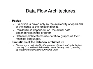

Data Flow Architecture
E N D
Presentation Transcript
Objectives • Introduction to Data Flow Architecture • Describe DFA in UML • Application domain of DFA • Benefit and limitation of DFA • Demonstrate • Batch sequential • Pipe and filter in OS • Java scripts
Overview • What is data flow architecture? • Whole system as transformation of successive sets of data. • System decomposed into modules. • Connection can be • IO Stream • Files, Buffers, Pipes • No interaction between modules • Modules do not need to know identity of each other
Block diagram of Data Flow Architecture Note: the architecture may allow loops
Categories of Data Flow Arch. • Many sub-categories exist • Batch Sequential • Pipe & Filter • Process Control • To adopt which one depends on the nature of the problem
Batch Sequential • Traditional data processing model • Widely used in 1950’s – 1970’s • Example: mainframe computers using COBOL Note: deployment can differ even for the same batch-sequential arch.
A Closer View Batch sequential in business data processing
Summary • Applicable Design Domains: • Data are batched • Benefits: • Simple division between sub-systems • Each sub-system can be a stand-alone • Limitation: • No interactive interface • No concurrency and low throughput • High latency
Pipe & Filters • Similar to Batch Sequence • Independent modules • Data connectors • Difference • Connectors are stream oriented • Concurrent processing
Basic Concepts • Data Source • Data Sink • Filter: independent data stream transformer • Reads data from input data stream • Process data and write to output stream • Does not wait for batched data as a whole • Does not even have to know identity of i/o streams • Pipe: data conduit • Moves data from one filter to another • Two types: character or byte streams
Data Flow Methods Three way to make data flow • Push only (Write only) • A data source may push data in a downstream • A filter may push data in a downstream • Pull only (Read only) • A data sink may pull data from an upstream • Filter may pull data from an upstream • Pull/Push (Read/Write) • A filter may pull data from an upstream and push transformed data in a downstream.
Classification of Filters • Active Filter: • pulls in data and push out the transformed data (pull/push) • It works with a passive pipe that provides read/write mechanisms for pulling and pushing. • Example: UNIX pipe. • Passive filter • Lets connected pipe to push data in and pull data out. • The filter must provide read/write mechanisms in this case.
Pipe & Filter In Unix • Unix provides pipe operation “|” • moves stdout from predecessor to the stdin of its successor • Example: • who | wc –l • Example: • $ mkfifo pipeA • $ mkfifo pipeB • $ grep a < pipeA >pipeB & • $ cat infile | tee pipeA | grep c |cat – pipeB | uniq –c
Explanation of Example • $ mkfifopipeA • $ mkfifopipeB • $ grep a < pipeA >pipeB & • $ cat infile | tee pipeA | grep c |cat – pipeB | uniq –c
Summary Pipe & Filter • Applicable Design Domain • System can be broken into a series of processing steps over data stream, in each step filter consumes and moves data incrementally. • Data format on the data stream is simple and stable, and easy to be adapted if it is necessary. • There are significant work which can be pipelined to gain the performance • Suitable for producer/consumer model
Advantages • Concurrency is high. • Reusability is easy – plug and play. • Modifiability: Low due to coupling between filters • Simplicity: Clear • Flexibility: High, very modular design • Lower latency
Disadvantages • Not suitable for dynamic interactions • Data standards (ASCII, XML?) • Overhead of data transformation among filters such as parsing is repeated in two consecutive filters • Difficult to configure a P&F system dynamically. • Error handling issue
Process Control Model • Suitable for embedded System • Composed of • Sub-systems • Connectors • Two types of sub-systems • executor processor unit • controller unit • System depends on: Control Variables
Data • Controlled variable: target controlled variable • E.g., Speed in a cruise control system • E.g., Temperature in an auto H/A system. • Input variable: measured input data • Manipulated variable: can be adjusted by the controller • E.g., motor rotation speed, etc.
Applicable Domains • Embedded software system involving continuing actions. • Needs to maintain an output data at a stable level. • The system has a set point which is the goal the system will reach and stay at that level.
Pros and Cons • Benefits • Better for situations where no precise formula for deciding the manipulated variable • Can be completely embedded • Limitations: • Requires more sensors to monitor system states