Download
1 / 31
310 likes | 443 Vues
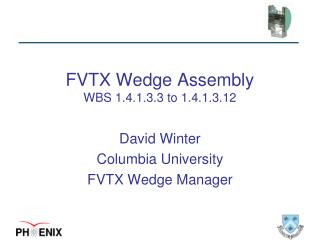
FVTX Wedge Assembly WBS 1.4.1.3.3 to 1.4.1.3.12. David Winter Columbia University FVTX Wedge Manager. Backplane. HDI. Detector. FPHX Chips. Thermally and electrically conductive adhesives. Thermally conductive adhesive. Talk Outline. Scope WBS 1.4.1.3.3 Attach HDI/Backplane

E N D
FVTX Wedge AssemblyWBS 1.4.1.3.3 to 1.4.1.3.12 David Winter Columbia University FVTX Wedge Manager
Backplane HDI Detector FPHX Chips Thermally and electrically conductive adhesives Thermally conductive adhesive Talk Outline • Scope • WBS 1.4.1.3.3 Attach HDI/Backplane • WBS 1.4.1.3.7 Bond Chips to HDI • WBS 1.4.1.3.12 Wirebond chips to HDI • WBS 1.4.1.3.8 Test Chips and HDI • WBS 1.4.1.3.4 Attach Sensor • WBS 1.4.1.3.5 Wirebond Sensor to Chips • WBS 1.4.1.3.6 Test Assembly • WBS 1.4.1.3.9 Encapsulation • Wedge Schedule • Procedure and Manpower • Status of Production • Summary ~10 cm D. Winter, FVTX Review November 2010
Scope • Work with vendor to: • Prepare assembly lab(s) • Develop assembly procedure • Receive backplanes, high-density interconnects (HDIs), sensors • All components arrive tested and qualified • HDIs populated with passive components • Assemble received components into wedges • Execute QA and testing procedures • Enter QA/Test results into database • Store assembled units • Deliver assembled wedges to detector assembly facility at BNL COMPLETED IN PROGRESS D. Winter, FVTX Review November 2010
Wedge Schedule Highlights of Dates Important to Wedge Assembly • 2nd Prototyping/design of components, fixtures: Completed • Procure and Q/A sensors: Completed • Procure HDI: In progress • Fabrication of backplanes: Completed • Procure Wedge Assembly fixtures: Completed • FNAL testing of production run of FPHX: Completed • Wedge assembly: 6/2/10 2/4/11 • WBS 1.4.1.3.3 Attach HDI to Backplane:6/2/10 11/29/10 • WBS 1.4.1.3.12 Wirebond FPHX to HDI 6/16/10 12/13/10 • WBS 1.4.1.3.5 Wirebond sensor to FPHX 7/7/10 1/6/11 • WBS 1.4.1.3.9 Encapsulation 8/4/10 2/4/11 • Endcap assembly (wedges onto disks): 11/8/10 3/9/11 Important dependencies • Critical path components: (Large) HDI D. Winter, FVTX Review November 2010
Main Highlights from Last Review • Prototyping assembly work complete • Several prototype modules • Fixtures prototyped and in process of revision • Sidet established that assembly is well within their technical expertise • Sidet provided production estimate • Production SOW in place • Poised to begin wedge production D. Winter, FVTX Review November 2010
Wedge Assembly Procedure (1) Sidet personnel Bond backplane to HDI Bond FPHX chips to HDI Wirebond FPHX chips to HDI FVTX personnel Chip readback Pulser test Bond sensor to HDI Wirebond sensor to FPHX Chip readback Pulser test Source Test Encapsulate wirebonds Chip readback Pulser test Source Test D. Winter, FVTX Review November 2010
Wedge Assembly Procedure (2) • Additional technical details • Arclad 7876 (50 micron thick) to laminate backplane, HDI, sensor and chips • Tra-con 2902 Silver Epoxy to provide conductivity between bias plane and sensor • Sylgard 186 for encapsulation • Assembly done in “batches” • Small wedges: groups of 5 at a time • Large wedges (projected): 3 (or more) at a time • Each step recorded in a traveler document • Originals kept at Sidet until end of project • Copy shipped with wedge • Traveler data also recorded in database for online search/access • QA Testing • Recorded in paper and electronic log • Recorded in database D. Winter, FVTX Review November 2010
Wedge Assembly in Action Assembly station Final Product! Chip Placement Encapsulation Wirebonding D. Winter, FVTX Review November 2010
QA and Testing of Wedges Basic Procedure includes: • Power up to verify low voltage and bias channels are operational • Download/readback of configuration to the FPHX chips • Threshold and noise measurements of the FPHX chips • Readout of strips in response to external stimulus (radioactive source) • Record results in database • Procedure calls for testing at various stages of assembly • Test single module at a time (current ROC limited to one wedge at a time) • Final qualification is performed after assembly completed and before shipping • In-place for the small production, and has been effective at identifying potential problems as early as possible, allowing us to correct them in a timely manner. • Example: Replaced FPHX chips: 3 (small) and 4 (large) D. Winter, FVTX Review November 2010
QA Procedure • Five tests performed • Scan output current settings (15 values) and record current draw for wedge at each • Scan Chip Ids and read back (default) values for each register • Scan Chip Ids, enable two channels and pulse once • Perform calibration (pulser) run • Place Sr90 source above wedge, take data for 15 min • For first iteration (sensor not yet mounted), source test is skipped • Total test time takes ~20 min (dominated by source time) • Simple user-friendly GUI D. Winter, FVTX Review November 2010
QA Setup PC LV supply HV Supply ROC Sr90 source held ~3in above wedge D. Winter, FVTX Review November 2010
QA Testing in Action Wedges mounted in rigid enclosure for testing Pass-through from clean room to test area Wedges transferred in ESD boxes Interface card Taking data D. Winter, FVTX Review November 2010
QA Results (Typical) • Calibration test with pulser: • Enable one channel at a time (on each chip at same time) • Scan through 63 pulser amplitudes • Pulse 100 times • Test duration = 30 secs • Source test: • Sr90 source @ ~3in • All channels enabled • Test duration = 15 min D. Winter, FVTX Review November 2010
Manpower Requirements • Assembly calls for Sidet technicians • Manpower- and time-intensive tasks require technical skill • Originally to be handled by senior techs, then load taken by junior techs as experience is gained • Assembly: Tech Supervisor, Sr/Jr Technician • Wirebonding: Tech Specialist, Sr/Jr Technician • Encapsulation: Technician • [Small wedges] In the end Tech Supervisor (Bert Gonzalez) did all micro-assembly • FVTX personnel in charge of testing • Requires 1-2 people for span of production time • AAronVeicht (Columbia Grad Student) on-site full-time • Dave Winter (Wedge Manager) on-site on rotating basis • Additional students and postdocs available from other institutions • Testing rate • Chips only: very rapid (typically 4-6 per hour), more than keeps up with production • With sensor: slower (typically 1-3 per hour), longer setup and running time D. Winter, FVTX Review November 2010
Status of Production Cost • In current estimate, production spans ~40 weeks • Primary bottleneck is wirebonding (31.5 weeks) • Testing takes place in parallel • Does not include attaching of pedestals or HDI bending • Quoted cost was $248k. Includes: • Labor • Materials and Services • Indirect • $65.5k spent (charged) to date • Represents ~25% of cost, produced 2/8 FVTX planes so far • On target with original estimate D. Winter, FVTX Review November 2010
Production Progress • Overall production has been extremely smooth and successful • Sidet is highly skilled & professional • Assembly & QA well-designed • Wealth of remote expertise • Small and Large HDIs began to arrive at Sidet in June 2010 • Large wedge production (of first articles) completed in June 2010 • 20 modules fully assembled and tested • Small wedge production completed Oct 2010 • 117 modules fully assembled and tested Integrated production D. Winter, FVTX Review November 2010
Production Statistics • Wedges were started and moved through assembly in batches (5 for small wedges) • Average number per week = 17 (21.2 excluding two worst weeks) • Peak per-week throughput = 34 • Bottlenecks • Wirebonding • Testing with sensor (setup is longer, source exposure is 15min) D. Winter, FVTX Review November 2010
Yields – Large Wedges • 25 HDIs delivered to UNM in May • 24 “passed” all tests • 23 shipped to Sidet • 23 wedges started • 20 wedges completely assembled and tested • 2 needed rework and are ready for encapsulation Paused due to readout card issues and start of small production • 1 has a bad HDI that slipped thru QA • Total of 299 FPHX chips placed! 20 fully working large wedges produced D. Winter, FVTX Review November 2010
Yields – Small Wedges • 120 sensors delivered to UMN • 118 passed all QA test and were delivered to Sidet • 120+ Small HDIs delivered to UNM in June • 120 wedge assemblies started (we thought we had 120 sensors) • 117 wedges fully assembled and tested • 1 wedge has sensor which draws too much current • Defies both fixes and explanation • Total of 1200 FPHX chips placed! • Including large wedges, grand total is 1499 • Only a handful of chips (< 8) had to be replaced 117 fully working small wedges produced D. Winter, FVTX Review November 2010
Production Problems (Injection Line1) • Some wedges developed a problem with the Side 1 pulse inject line • They produce no response to pulses on Side 1 • They work fine in response to a source • Develops over time (ie. all HDIs passed their tests at UNM) • Currently affects 39/118 small wedges D. Winter, FVTX Review November 2010
Inject 1 Investigation Top Layer • Side 1 inject is the only trace to run along bottom layer • This means it connects to the input pin by way of via thru all 7 layers • Systematically probed points along trace to find source of break • Concluded the break was at/near via on bottom surface • Not seen so far in large wedges, but steps have been taken by Dynconnex to minimize this happening in the current run. • Solution is to hand-solder a wire from input pin to the trace, bypassing weak area. Bottom Layer D. Winter, FVTX Review November 2010
Production Plans • Impact of large HDI delay • Directly delays production • Current estimate has HDIs arriving at Sidet ~ mid-Dec. • Potential schedule compression drives need to economize in two places: • Sidet through-put: Increase personnel • Train a “Second Bert” for chip placement • DES project has completed at Sidet, giving us two full-time wirebonders • Testing through-put: Improvements in order of preference/ease: • More active Sr90 source to reduce exposure time • Adopt testing shifts (obviously requires second person) • Add second test station • Nominally should allow a doubling of throughput (originally 5 per day, double that to 10 per day) D. Winter, FVTX Review November 2010
Schedule (with higher throughput) • Ends 2/22/11: • 14 wks from now • Includes holidays • (6 wks @ 50/wk) D. Winter, FVTX Review November 2010
Summary • Wedge assembly comprises WBS items 1.4.1.3.3 –1.4.1.3.12 • Small wedge production completed • Very smooth, no major issues • Spanned June – Oct 2010 • 117 working wedges (needed 96+8) • High yield due to both well-designed assembly and QA procedures • Large wedge production to restart in mid-Dec • Dependent on HDIs – projecting week of 20th Dec • Duration should be 6 weeks • Doubling throughput will ensure assembly can maintain schedule D. Winter, FVTX Review November 2010
Backup slides D. Winter, FVTX Review November 2010
Example Traveler Document D. Winter, FVTX Review November 2010
Traveler Web Interface D. Winter, FVTX Review November 2010
Production Problems (Minor examples) Occasionally FPHXs do chip during wirebonding Procedure exists to replace damaged chips In one case, HDI “lost” a chip id pad Confirmed with probe station Wirebonded to good pad D. Winter, FVTX Review November 2010
Managing the Schedule • Input constraints • Wedges are started in batches, and more or less move thru system that way • Between chip placement and wirebonding, arclad needs about 2 hours to “harden” • Testing keeps pace with production (latency problems with source testing are solved) • Ag epoxy needs at least 4 hours curing to be effective • Assume 2 batches of 5 at a time • Note: • Chip placement, wirebonding and encapsulation scale with size (various amounts) • Other tasks do not • 5/batch considered average – will be slower at start, and faster later D. Winter, FVTX Review November 2010
Silicon Detector Center @ FNAL • Primier facility for building and testing vertex detectors for HEP experiments • Five large-scale clean rooms for assembly and testing • Several wirebonding stations • Wide expertise with Silicon and CCD technology • CDF, D0, CMS, SNAP among others D. Winter, FVTX Review November 2010
Example of managed process flow D. Winter, FVTX Review November 2010