Download
1 / 17
700 likes | 1.84k Vues
Lecture 20: The mechanism of plastic deformation. PHYS 430/603 material Laszlo Takacs UMBC Department of Physics. Original defect-free crystal Elastic deformation: bonds are compressed and stretched, but not broken. Plastic deformation by the introduction of dislocations.

E N D
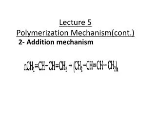
Lecture 20: The mechanism of plastic deformation PHYS 430/603 material Laszlo Takacs UMBC Department of Physics
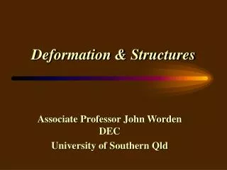
Original defect-free crystal Elastic deformation: bonds are compressed and stretched, but not broken. Plastic deformation by the introduction of dislocations. Dislocations organize into parallel lines, forming low-angle grain boundaries. Recrystallization via annealing: defect free sample with new shape is obtained.
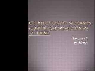
Engineering stress-strain curve - the most important source of information on the plastic properties of a material - for impure iron and for copper. Notice the Lüders region for iron and the more substantial strain hardening of copper.
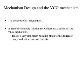
Plastic deformation • Macroscopically it is always shear. Compression and tension do not result in plastic deformation directly. • Microscopic mechanisms: • Slip mediated by dislocations is the most important mechanism by far. • Mechanical twinning is active only if slip is not possible. • Creep by thermally activated diffusion over time.
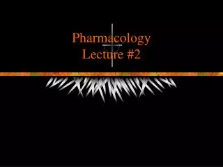
100 mm Surface roughening of an AlMg(0.8%) alloy due toplastic deformation in tensionImage by confocal optical microscopy.Eric Moore, Ph.D. Thesis, UMBC 2006
Twinning results in plastic deformation. It is a cooperative phenomenon, layers of atoms must move simultaneously. Consequently, it requires large local stress.
Shear stress required for slip The theoretical shear stress is estimated assuming that an entire layer of atoms moves simultaneously. Assume that the potential felt by atoms is For very small displacement, well within the elastic limit From here the theoretical shear strength can be expressed. It is typically three orders of magnitude too large, yet a useful reference:
Peierls stress: the stress required for slip by the movement of a dislocation. If b = d and Slip is easiest for planes with low Miller indeces, that is for small b and large d. Peach-Koehler equation The displacement of a dislocation relates to work done by the external stress, thus we can introduce the concept of “force” on a dislocation. This is not a force in the sense of Newton’s second law; dislocations do not have a mass and they are not accelerated by a force. But equilibrium of forces on a dislocation remains a valid concept.
In fcc, d is the largest for the {1 1 1} planes, the dominant slip system is {1 1 1}<1 1 0>. Notice that we need to give the slip plane and the slip direction within the plane. In fact, this is the only active slip system, but there are 12 different combinations: 4 different {1 1 1} planes and 3 different slip directions/ edge directions for each. This many slip systems can easily mediate any shape change. (The minimum number of slip systems required is 5.) Notice that the actual geometry of dislocations depends on the crystal structure - it is not like the square grid used for illustration.
100 mm Slip lines in AlThe orientation of the individual crystallite determines which slip system(s) are active.
A dislocation may break into two parallel partial dislocations separated by a band of stacking fault. The magnitude of dislocation and stacking fault energies determines whether this indeed happens and how far the two partials separate from each other.
A full dislocation moves atoms from one position to and equivalent one. In fcc, this can split easily into two partials according to the equation (Shockley partial dislocation) a/2 [1 -1 0] a/6 [2 -1 -1] + a/6 [1 -2 1]
If c/a < 1.63, other slip systems become available, the material is ductile (Ti). For c/a > 1.63, the material is either brittle, or the deformation takes place in part by twinning. At the theoretical 1.63 c/a ration, the {0 0 0 1}<1 1 -2 0> system is identical to the slip system of fcc. But it operates in only one plane (the basal plane) and three possible directions. Not sufficient for an arbitrary shape change that would require at least five slip systems.
In the bcc structure, there is the <1 1 1> direction in which atoms are in direct contact; it defines the slip direction. But slip can take place almost equally easily along three different slip planes; {1 1 0}<111> is the best. With many active slip systems, bcc metals are quite ductile, although not as much as fcc, as the slip planes are not close packed. In more complicated lattice structures - larger b/d - slip is more difficult. Complex compounds, including intermetallic phases, are usually brittle. This is an important consideration technologically.
Relationship between applied stress and stress on a slip plane Although we usually put the sample under tension or compression, slip takes place due to shear along the slip system that reaches the critical shear stress first. If tension is applied, the resulting shear stress is = cos() cos() Here cos() comes from taking the component of F in the direction of the slip and cos() describes the fact that this force acts on the larger cross section A/ cos(). The sheer stress is the largest when the slip direction is in the plane of F and N. In this case + = 90°, = sin() cos(). This expression is the largest when = 45°. As a result, slip takes pace at 45° in isotropic materials.
Preferred slip systems for some metals Notes • The easiest slip for Ti is not along (0 0 0 1) • Impurities usually increase the critical shear stress.
Except for a core about as wide as a single line of atoms, a dislocation can be represented with its elastic stress field. This is useful to calculate the energy of the dislocation. The result depends on the type of dislocation, but it is of the order of E(d) = 1/2 G b2 per unit length.