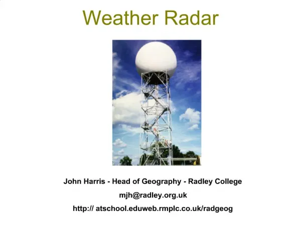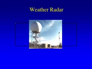
Weather Radar
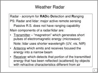
Weather Radar. Radar - acronym for RAD io D etection and R anging PS: Radar and lidar: major active remote sensing Passive R.S. does not have ranging capability Main components of a radar/lidar are:

Weather Radar
E N D
Presentation Transcript
Weather Radar Radar - acronym for RADio Detection and Ranging PS: Radar and lidar: major active remote sensing Passive R.S. does not have ranging capability Main components of a radar/lidar are: • Transmitter – “magnetron” which generates short pulses of electromagnetic energy (microwave) Note: lidar uses shorter wavelength (UV, vis, NIR) • Antenna which emits and receives focused the energy into a narrow beam • Receiver which detects that portion of the transmitted energy that has been reflected (scattered) by objects with refractive characteristics different from air
Diagram of Radar Transmission and Reception (Fig. 1.1 from Batan and Fig. 8.1 from Stephens)
Basic Operation Principles • Electromagnetic energy is transmitted into the atmosphere. Once reaching a target (cloud droplets, ice crystals, rain drops, snowflakes, aerosol particles, insects, birds, airplane, etc.), the energy is absorbed and scattered. A portion of backscattered energy is received and processed by a radar to display as an echo. • Two types of radar Conventional radar – incoherent radar (1-2o beam width) Detect only the intensity or the amplitude of the electromagnetic energy – an incoherent sys Doppler radar – coherent (phase) radar Detect both the amplitude and phase of the electromagnetic energy.
range - r Target Transmitter Weather Radar:Important Relationships pulse of energy time for light to reach target = r/c time for light to reach receiver = r/c total time = 2r/c; r = ct/2 where c is the speed of light C=3x10⁸ m/sec = 3x10⁵ km/sec Received Power r = ct/2
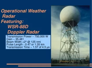
Important Radar Parameters • Peak Power - Pt - (instantaneous power emitted in a pulse) 10 < Pt < 5000 kW, 5x10⁶ W • Minimum detectable signal Much smaller than emitted energy ~ 10-13 W Because of the large range of the energy dealt with in a radar system (10-13 ~106), the power is often expressed in decibels (dB). Difference between two power level p1 and p0 is given by p(dB) = 10 log10(p1/p0) So, the dynamic range of a radar ~ 190 dB in electronic term, po = 1 mW (10-3 W), unit dBm Minimum detectable ~ -100 dBm Peak power ~ 90 dBm
Important Radar Parameters (Cont.) • Radio frequency - Radio wavelength - - (c/ 3 < GHz (1 GHz = 109 sec-1) (wavelengths from 1 to 30 cm) Detection capability of hydrometeor depends critically on radio frequency/wavelength. In general, the smaller the size of the particles, the shorter the wavelength required to detect. e.g. the popular 10 cm (3 GHz or S-band) radar can detect rain drops but not cloud droplets which may be detected by 95 or 35 GHz radar.
Radar Important Parameters (Cont.) • Pulse repetition frequency (fr) (PRF) Typical PRF for weather radar fr = 1000 s-1 but may range between 200 – 2000 s-1 • Maximum range of detection for a radar set half the interval between pulses times the speed of light: c/2fr ~ 150 km for fr = 1000 s-1 range: 750km < c/2fr < 75 km • Pulse duration: 0.1 < < 5 µs vs. pulse interval 500 < t < 5000 µsec
Important Radar Parameters - cont. • Beam width - angular separation between points where the transmitted intensity has fallen to 1/2 its maximum value (i.e., 3 dB below the maximum) The smaller the beam width, the better the resolution. Typical width for weather radar 1o-3o Imax Beam Width .5 *Imax Intensity 0 Angular Separation
Summary of Important Radar Parameters and “Typical Values”(c.f. The appendix of Battan) • Peak Power ~ 100-1000kW or 80~90 dBm • Minimum Detectable Signal ~ 10-13 W or –100 dBm • Radio Frequency The popular weather radar 5~10 cm • Pulse Repetition Frequency PRF ~ 1000 sec-1 • Pulse duration: 0.1 < < 5 µsec • Beam width: 1o-3o
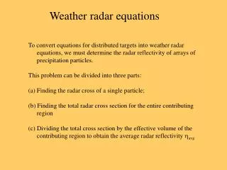
Radar Range EquationDerivation The Radar Range Equation relates received power to the backscatter cross section of the target. Note: the radar equations given here invoke some assumptions and thus differ from the more precise eqs. used in operation. More exact ones found in Radar Observation of the Atmosphere by Battan. Assume the radar transmits peak power Ptisotropically without attenuation.Using the inverse-square law, the power intercepted P by a target of area At at a distance r from the transmitter is
Radar Range EquationDerivation - cont. But, the antenna focuses the energy into a narrow beam, thereby increasing the power relative to an isotropic source. Thus the power intercepted is where G is a dimensionless number (ratio of peak intensity to uniform) called the antenna axial Gain.
But the gain and aperture area are related approximately as Radar Range EquationDerivation - cont. Assume the target scatters the power intercepted isotropically, then the power returned Pr to the antenna with aperture area Ae is given as Thus,
Radar Range EquationDerivation - cont. But, most targets do not scatter isotropically, and as a convenient artifice the back scatter cross-section is introduced such that and ≠ At. The ratio /At vary with target property and size and the frequency of a radar. For small target (w.r.t. radar wavelength), the ratio increases exponentially with particle size (Rayleigh approximation).
Hail with a water coating scatters more radiation back. INSERT FIG. 4.2 FROM BATTAN
Weather Radar Equation • Rain, snow and cloud particles are examples of distributed targets - many scattering elements that are simultaneously illuminated by the transmitted pulse. • The volume containing those particles that are simultaneously illuminated is called the resolution volume given by the beam width and pulse length. • Power returned from a given range fluctuates because precipitation particles move. • Instead of using the instantaneous power received, the radar range equation is formulated in terms of the average signal received from a given volume.
Weather Radar Equation - cont. For averages over about 10-2 s, the average received power may be written as: where the summation is over the backscatter cross-sections within the resolution volume. In order to relate the received power to propertiesof the precipitation, we must now find an expressionfor .
where Rayleigh Scattering Define the scattering size parameter for a sphere as the ratio of the circumference of the sphere to the wavelength. Also called “electrical size.” For << 1, e.g. for r0~1mm and 10cm radar, =0.06 scattering is in the Rayleigh region, and for a sphere or radius ro is given as m is the complex index of refraction and n is the ordinary refractive index and k the absorption coefficient.
Weather Radar and Rayleigh Scattering the refractive terms depends upon , T and composition of the scatterer. For the meteorological range of temperatures and for common wavelengths liquid water - ||2 ≈ 0.93 ice ||2 ≈ 0.21 Thus, an ice sphere has a radar cross-section only about 2/9 that of a water sphere of the same size. For water-coated hailstone, k and varies strongly with water content, ranging from well below the values for ice to significantly higher than those for pure water. The later often displayed as a “bright band” in the radar screen, often associated with light precipitation in mix-phase clouds.
Weather Radar Equation - cont. Assuming Rayleigh scattering spheres of diameter D Introduce the radar reflectivity factor Z, where where the summation extends over a unit volume, and N(D)dD is the number of drops per unit volume of a given diameter.
Weather Radar Equation - cont. After accounting for the scattering volume and the beam pattern, the most useful weather radar range equation is: radar target where is the pulse duration and is the beam width in radians. Note that in some instances, Rayleigh scattering may not be fulfilled. In such instances, Z should be replaced by Ze, the effective radar reflectivity factor.
Weather Radar Equation - cont. • Power in decibels is related to the reflectivity factor as measured on the decibel scale. • Pr - measured in milliwatts, 10 log Pris the power in dBm (decibels relative to a milliwatt). • Z is measured in mm6/m3 and 10 log Z is the reflectivity factor in dBz. where C is a constant determined by radar parameters and dielectric characteristics of the target
Major Assumptions behind the Radar Equation • The targets are spheroid For non-spherical targets, polarization needs to be taken into account. The effect is measured by “depolarization ratio” of the cross-polarized component (Pc) over parallel-polarized component (Pp).
No attenuation between the target and radar • Pending the wavelength of radar beam, attenuation may be caused by radome, atmospheric gases, clouds, and precipitation due to both absorption and scattering. • For radar of 10 cm or longer wavelength, all attenuations are insignificant. • For radar of a few cm, gas attenuation is negligible, but cloud and rain attenuations need to be considered. • For radar of less than 3 cm, all attenuations needs to be considered. Ice cloud attenuation is less than water clouds by two orders of magnitude and is thus often neglected. • Because of attenuation, the shorter the wavelength, the shorter the detection range.
Some empirical data on R and Z give Relationship Between Z and Rainfall Rate For a Marshall-Palmer distribution function for R in mm/hr and Z in mm6/m3. For snow, Z = 2000 R2 The minimum detectable rainfall rate ≈ 0.1 mm/hr.
Some empirical data on R and Z give Relationship of dBz to rain rates.
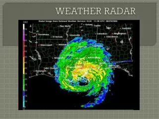
Radar Displays PPI - Plan position Indicator (rotating scan) Maps the received signals on polar coordinates in the plan view. The antenna scans 360° at fixed elevation angle. At every azimuth the voltage output of the receiver as a function of range is used to intensity-modulate a tube with polar coordinates (Rogers and Yau, 1989). This produces a plane view of the distribution of precipitation. Without careful calibration, PPI records are only useful to show the location and time of occurrence of precipitation.
Radar Displays - cont. RHI - Range Height Indicator This display is generated when the antenna scans in elevation with fixed azimuth, thereby showing the details of the vertical structure of precipitation. CAPPI - Constant Altitude PPI Azimuth and altitude are varied systematically to survey region surrounding the radar site.
PPI RHI
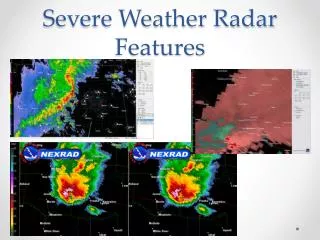
Radar Displays - cont. Doppler Radar The frequency of the transmitted signal for certain radars is constant. The frequency of the returned signal is compared with the transmitted signal, and the frequency (Doppler) shift is interpreted as the radial velocity of the precipitation r(hat) unit vector in radar pointing direction.
The combination of a low tilt angle and an inversion at and near the Earth's surface promotes an abundance of ground clutter. Below left is an example radar images using the lowest tilt angle (0.5 degrees) taken in the morning when a radiation inversion was in place. Right more typical NEXRAD ground clutter.
RADAR Take Home Messages1. P(dB) = 10 log (P/Po)2. c ~ 300 m/ms; Pulse Rep. Freq ~ 1000 Hz; Distance between pulses = ½ 300 x 103ms = 150 km. This is the range limit without overlap.3. Doppler (phase coherent) provides radial velocity.4. Atmospheric window 1.0 to 30 cm. Longer wavelengths cannot see cloud droplets.5. Ice scatters only about 2/9 of liquid water. 6. Bright band at freeing level.7. Attenuation ~ 1/l implies 10 cm radar sees farther, but needs a bigger dish.