Download
1 / 18
180 likes | 362 Vues
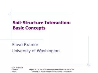
SOIL-STRUCTURE INTERACTION IN NONLINEAR SOIL by V. Gicev a ),b) a) Rudarsko-geoloski fakultet, Goce Delcev 89, 2000 Stip, Republic of Macedonia b) Fakultet za informatika, Krste Misirkov bb, 2000 Stip, Republic of Macedonia. Systems with rigid foundation Trifunac (1972)

E N D
SOIL-STRUCTURE INTERACTION IN NONLINEAR SOIL byV. Giceva),b)a) Rudarsko-geoloski fakultet, Goce Delcev 89, 2000 Stip, Republic of Macedoniab) Fakultet za informatika, Krste Misirkov bb, 2000 Stip, Republic of Macedonia
Systems with rigid foundation Trifunac (1972) Wong and Trifunac (1974) Wong and Trifunac (1975) Westermo and Wong (1977) Luco and Wong (1977) V.W. Lee (1977) Systems with flexible foundation Todorovska et al.(2001) Hayir et al. (2001) Aviles et al. (2002) Gicev (2005) Two types of models of soil-structure system depending upon the rigidity of foundation: • Main features of the soil-structure interaction phenomenon: • wave scattering, • radiation damping, • reduction of the system frequencies. • In this paper, the influence of interaction on the development of nonlinear zones in the soil is studied. • The problems that should be addressed in numerical studies of the nonlinear soil-structure interaction: • Heterogeneities and discontinuities of the soil medium • Modeling of the free surface • Artificial boundaries • Keeping track of the nonlinear constitutive law at each point in the soil
ENERGY AND PERMANENT STRAIN DISTRIBUTION (3.1) (3.2) As a test example, the properties of Holiday Inn hotel in Van Nuys, CA in east-west direction are considered (Blume and Assoc.,1973). The displacement, the velocity, and the linear strain in the soil (bs= 250m/s) during the passage of plane wave in form of half-sine pulse are: (3.3) Generally, the yielding strain can be written as (3.4) In the last equation, C is a constant that controls the yielding strain in the soil. Depending upon C, three cases of nonlinear response can be distinguished: Small nonlinearity. Permanent strain does not occur until the wave hits the foundation with any angle of incidence. Intermediate nonlinearity. Permanent strain does not occur until the wave is reflected from the free surface or is scattered from the foundation, for any angle of incidence. Permanent strain will or will not occur after the reflection of the incident wave from the free surface depending upon the angle of incidence. Large nonlinearity. Permanent strain occurs after reflection from the free surface. Permanent strain may or may not occur before the wave reflects from the free surface, depending upon the angle of incidence. In this paper, we consider cases of small and intermediate nonlinearity.
ENERGY DISTRIBUTION IN THE SYSTEM The energy flow through given area is defined in terms of a plane wave approximation (Aki and Richards 1980) as: where rs and bs are density and shear wave velocity of the soil and v is a particle velocity, which for our pulse is given by equation (3.2). Asn is the normal area through which the wave is passing. For our geometry settings of the soil island (Fig.1), the area normal to the wave passage is: (3.6) Putting equations (3.2) and (3.6) into (3.5) and integrating,the analytical solution for the input wave energy in the model (red arrows in Fig.7) is (3.7) Because the short pulses are low pass filtered up to wc=200rad/s (Fig. 2a and 2b), the analytical and the numerical solution (3.5) for input wave energy do not coincide (Fig.8)
Energy going out from the model, Eout, is computed using Eq. (3.5). • Hysteretic energy (energy spent for creation and developing of permanent strains in the soil) is computed from: - Instantaneous energy in the building is computed from: The sum of the last three types of energy, should balance the input energy as shown on Fig. 9.
To study the effect of scattering from the foundation only, the building is considered high enough, so that the reflected wave from the top of the building cannot reach the building-foundation contact during the analysis. The analysis is terminated when the wave completely exits the soil island. In this study, the hysteretic and the energy in the building are subjects of interest. On Fig.10 these two types of energies are presented as functions of the dimensionless frequency.
DISTRIBUTION OF THE PERMANENT STRAIN IN THE SOIL Considering Fig.11 and starting from dynamic equilibrium of the differential hexahedron on Fig.11, one can find the principal stress in the considered point and its direction as: and In the following figures, the principal permanent strain is illustrated for the case of intermediate nonlinearity (C=1.5), for two angles of incidence q = 300 and q = 600 and for three foundation stiffness bf = 250m/s; 500m/s; and 1000m/s.
Small nonlinearity C = 1.73 Fig.13a Principal permanent strain in the soil for h = 0.1, two angles of incidence, and three foundation stiffness. C = 1.73
Small nonlinearity C = 1.73 Fig.13b Principal permanent strain in the soil for h = 0.5, two angles of incidence, and three foundation stiffness. C = 1.73
Small nonlinearity C = 1.73 Fig.13c Principal permanent strain in the soil for h = 1, two angles of incidence, and three foundation stiffness. C = 1.73
Intermediate nonlinearity C = 1.5 Fig.14a Principal permanent strain in the soil for h = 0.1, two angles of incidence, and three foundation stiffness. C = 1.5
Intermediate nonlinearity C = 1.5 Fig.14b Principal permanent strain in the soil for h = 0.5, two angles of incidence, and three foundation stiffness. C = 1.5
Intermediate nonlinearity C = 1.5 Fig.14c Principal permanent strain in the soil for h = 1, two angles of incidence, and three foundation stiffness. C = 1.5
CONCLUSIONS • Numerical methods are powerful tools for studying the nonlinear soil-structure interaction problems. • Because of grid dispersion, selection of the grid spacing should be done carefully. • Short waves cannot be reconstructed even with very fine grids, and the incident wave (pulse) should be low-pass filtered to utilize numerical methods effectively. • For small angles of incidence (close to vertical incidence), the permanent strains in y direction are dominant, while for big angles of incidence (close to horizontal incidence), the permanent strains in x direction are dominant. • For long waves and small angles of incidence (Fig.12a, q=300), the effect of the interaction on nonlinear response of soil is small. • For soft foundation, bf = 250m/s and small incident angles (Fig.12a,b,c,d at the left top corner), the effect of the interaction on nonlinear response of soil is also small. • As foundation becomes stiffer, zones of large permanent strains develop around the foundation. • For stiff foundation, short waves (h = 1 and h = 2), and big incident angles, zone of permanent strains develops behind the foundation. This appears to be due to concentration of rays associated with diffraction of the waves from the foundation. • The zones of large permanent strains shown in Fig.12a,b,c,d are responsible for failures of the shallow infrastructure (pipes, underground cables etc.) which accompany large earthquakes and cause interruption of electric and water supply.