Download
1 / 42
420 likes | 434 Vues
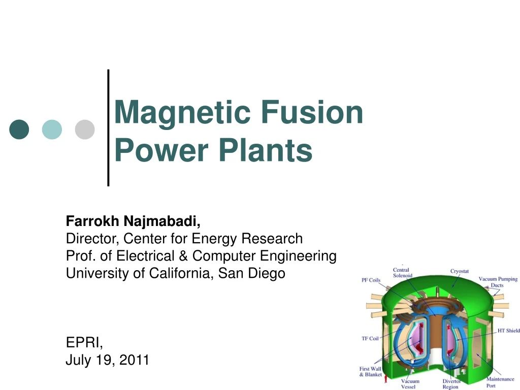
Magnetic Fusion Power Plants. Farrokh Najmabadi, Director, Center for Energy Research Prof. of Electrical & Computer Engineering University of California, San Diego EPRI, July 19, 2011. Conceptual designs studies of fusion power plants are performed by the ARIES national team.

E N D
Magnetic Fusion Power Plants Farrokh Najmabadi, Director, Center for Energy Research Prof. of Electrical & Computer Engineering University of California, San Diego EPRI, July 19, 2011
Conceptual designs studies of fusion power plants are performed by the ARIES national team National ARIES Team comprises key members from major fusion centers (universities, national laboratories, and industry). Many studies of evolving confinement concepts and different technologies.
Scientific & Technical Achievements Projections and Design Options R&D Needs and Development Plan Framework: Assessment Based on Attractiveness & Feasibility Goals and Requirements Periodic Input from Energy Industry Evaluation Based on Customer Attributes Attractiveness Characterization of Critical Issues Feasibility No: Redesign Yes Balanced Assessment of Attractiveness & Feasibility
Utility/industrial advisory committees have defined customer requirements * See http::/aries.ucsd.edu/ARIES/DOCS/UAC/ for membership and meeting minutes. • Fusion Power Plant Studies Utility Advisory Committee and EPRI Fusion Working Group* • Chaired by Steve Rosen & Jack Kaslow respectively, • Met biannually in 1993-1995. • Helped define goals and top-level requirements. • Had a major impact on safety/licensing as well as configuration/maintenance approach. • Input as members of review committee for individual designs.
Fusion physics & technology Low-activation material Goals & Top-Level Requirements for Fusion Power Plants Were Developed in Consultation with US Industry • Have an economically competitive life-cycle cost of electricity • Gain Public acceptance by having excellent safety and environmental characteristics • No disturbance of public’s day-to-day activities • No local or global atmospheric impact • No need for evacuation plan • No high-level waste • Ease of licensing • Reliable, available, and stable as an electrical power source • Have operational reliability and high availability • Closed, on-site fuel cycle • High fuel availability • Available in a range of unit sizes Fusion Fuel Cycle
Scientific & Technical Achievements Projections and Design Options R&D Needs and Development Plan Framework: Assessment Based on Attractiveness & Feasibility Goals and Requirements Periodic Input from Energy Industry Evaluation Based on Customer Attributes Attractiveness Characterization of Critical Issues Feasibility No: Redesign Yes Balanced Assessment of Attractiveness & Feasibility
Detailed analyses are necessary to understand trade-offs Plasma analysis Engineering Design System Analysis and Trade-offs Self-consistent point design for a fusion power plant
Detailed analyses are necessary to understand trade-offs Plasma analysis Engineering Design • Superconducting magnet design • First wall/blanket, and shield, • Divertor; • Current-drive systems (Launchers, transmission lines, sources) ,… • Configuration • Neutronics & Shielding • Thermo-fluid & thermo mechanical design • MHD effects • Tritium Breeding & management • Erosion • Off-normal events • Inventory • Waste Disposal • Safety Analysis • Maintenance System Analysis and Trade-offs Self-consistent point design for a fusion power plant High accuracy equilibria; Large ideal MHD database over profiles, shape and aspect ratio; RWM stable with wall/rotation or wall/feedback control; NTM stable with LHCD; Bootstrap current consistency using advanced bootstrap models; External current drive; Vertically stable and controllable with modest power (reactive); Rough kinetic profile consistency with RS /ITB experiments, as well GLF23 transport code; Modest core radiation with radiative SOL/divertor; Accessible fueling; No ripple losses; 0-D consistent startup;
D + T 4He (3.5 MeV) + n (14 MeV) n T n + 6Li 4He (2 MeV) + T (2.7 MeV) DT Fusion requires a tritium-breeding blanket * A neutron multiplier, e.g., 7Li, Pb, or Be, is needed to achieve tritium self-sufficiency. Plasma should be surrounded by a blanket containing Li • Through care in design, only a small fraction of neutrons are absorbed in structure and induce radioactivity* • Rad-waste depends on the choice of material: Low-activation material • For liquid coolant/breeders (e.g., Li, LiPb), most of fusion energy (carried by neutrons and n-Li reaction) is directly deposited in the coolant simplifying energy recovery • Issue: Large flux of high-energy neutrons through the first wall and blanket:
Irradiation leads to a operating temperature window for material Structural Material Operating Temperature Windows: 10-50 dpa Radiation embrittlement Thermal creep Zinkle and Ghoniem, Fusion Engr. Des. 49-50 (2000) 709 Carnot=1-Treject/Thigh • Additional considerations such as He embrittlement and chemical compatibility may impose further restrictions on operating window
New structural material should be developed for fusion application Candidate “low-activation” structural material: • Fe-9Cr steels: builds upon 9Cr-1Mo industrial experience and materials database • 9-12 Cr ODS steel is a higher-temperature option. • SiC/SiC: High risk, high performance option (early in its development path) • W alloys: High performance option for PFCs (early in its development path)
Many Blanket Concepts have been considered • 2) Li (breeder and coolant) with vanadium structure • Needs insulating coating for MFE (MHD effects). • Special requirements to minimize threat of Li fires. • Large tritium inventory in Li which can be released during an accident. • 1) Ceramic Solid Breeder Concepts (using He coolant and ferritic steel structure) • Adopted from fission pebble-bed designs. • Complex internal design of coolant routing to keep solid breeder within its design window. • High structural content, low Li content, requires lots of Be multiplier. • Low outlet temperature and low efficiency • Large tritium inventory
3. Dual coolant with a self-cooled PbLi zone, He-cooled RAFS structure and SiC insert • Steel First wall and partitioning walls are cooled with He. • Most of fusion neutron energy is deposited in PbLi coolant/breeder. • SiC insert separates PbLi from the walls: They reduce a) MHD effects and b) heating of the walls by LiPb • Outlet coolant temperature of ~700oC (Max. steel temperature of ~550oC)
4. High-performance blanket with SiC Composite Structure and LiPb coolant Outboard blanket & first wall • Simple, low pressure design with SiC structure and LiPb coolant and breeder. • Innovative design leads to high LiPb outlet temperature (~1,100oC) while keeping SiC structure temperature below 1,000oC leading to a gross thermal efficiency of ~ 59% (52% net) • Simple manufacturing technique. • Very low afterheat. • Class C waste by a wide margin.
Scientific & Technical Achievements Projections and Design Options R&D Needs and Development Plan Framework: Assessment Based on Attractiveness & Feasibility Goals and Requirements Periodic Input from Energy Industry Evaluation Based on Customer Attributes Attractiveness Characterization of Critical Issues Feasibility No: Redesign Yes Balanced Assessment of Attractiveness & Feasibility
The ARIES-AT utilizes an efficient superconducting magnet design • On-axis toroidal field: 6 T • Peak field at TF coil: 11.4 T • TF Structure: Caps and straps support loads without inter-coil structure; Superconducting Material • Either LTC superconductor (Nb3Sn and NbTi) or HTC • Structural Plates with grooves for winding only the conductor.
Configuration & Maintenance are important aspects of the design vacuum vessel Inner part: 4 pieces, Complete vessel, outer part is welded during assembly entirely made of maintenance ports Install 4 TF coils at a times Insert ¼ of inner VV and weld Complete the torus Insert maintenance ports and weld to inner part of VV and each other Install outer walls and dome of the cryostat
Modular sector maintenance enables high availability • Full sectors removed horizontally on rails • Transport through maintenance corridors to hot cells • Estimated maintenance time < 4 weeks ARIES-AT elevation view
ARIES-AT Fusion core is segmented to minimize rad-waste and optimize functions Shield Divertor 1st Out-board FW/blanket 2nd Out-board FW/blanket Inboard FW/blanket Shield Stabilizing shells Blanket-2 and shield are life-time components
After 100 years, only 10,000 Curies of radioactivity remain in the 585 tonne ARIES-RS fusion core. Radioactivity levels in fusion power plantsare very low and decay rapidly after shutdown • SiC composites lead to a very low activation and afterheat. • All components of ARIES-AT qualify for Class-C disposal under NRC and Fetter Limits. 90% of components qualify for Class-A waste. Ferritic Steel Vanadium Level in Coal Ash
Safety analysis of off-normal events and accident scenarios indicate no evacuation plan is needed • Detailed accident analysis (e.g., loss of coolant, loss of flow, double break in a major coolant line) are performed: • Limited temperature excursion due to the use of low-activation material. • No evacuation plan is needed. Most of the off-site dose after an accident is due to tritium release from fusion core. Fusion core tritium inventory is ~ 1kg. • Components are designed to handle off-normal events: • Pressurization of blanket modules due internal break of He channels (Dual-cooled blanket) • Disruption forces and thermal loads • Quench of TF coils
Waste volume is modest (ARIES-AT) • 1,270 m3 of Waste is generated after 40 full-power year of operation. • Coolant is reused in other power plants • 29 m3 every 4 years (component replacement), 993 m3 at end of service • Equivalent to ~ 30 m3 of waste per full-power operation. • Effective annual waste can be reduced by increasing plant service life. • 90% of waste qualifies for Class A disposal
A cost break-down structure is used. • No. Account • Land and Land Rights • Structures and Site Facilities • Power Core Plant Equipment • 22.01 Fusion Energy Capture and Conversion • 22.01.01 First Wall and Blanket • 22.01.02 Second Blanket • 22.01.03 Divertor Assembly • 22.01.04 High Temperature Shielding • 22.01.05 Low Temperature Shielding • 22.01.06 Penetration Shielding • 22.02 Plasma Confinement • 22.02.01 Toroidal Field Coils • 22.02.02 Poloidal Field Coils • 22.02.03 Feedback Coils • 22.03 Plasma Formation and Sustainment • 22.04 …. 22.14 • Turbine Plant Equipment • Electric Plant Equipment • Miscellaneous Plant Equipment • Heat Rejection Equipment • Special Materials • Direct Cost • 91-98 Indirect Costs • 99. Total Cost *J. Delene, Fusion Technology, 26 (1994) 1105. • Costing is performed through a comprehensive cost break-down structure to component level. • Direct vendor quotes are used when available. • In the absence of vendor quotes, comparable technologies are used to cost a component. • Costing assumptions where calibrated against advanced fission and fossil plant economics.*
Estimated Cost of Electricity (2009 c/kWh) Major radius (m) Magnetic Fusion Power Systems are projected to be cost-competitive. • Total Capital Cost ranges from $4B to $8B. • We are in the process of implementing Gen IV fission cost data base. This data base would lead: • Similar total Capital Cost • 30% lower COE because of a lower fixed-cost rate (5.8% for Gen-IV vs 9.65% for Delene).
Scientific & Technical Achievements Projections and Design Options R&D Needs and Development Plan Framework: Assessment Based on Attractiveness & Feasibility Goals and Requirements Periodic Input from Energy Industry Evaluation Based on Customer Attributes Attractiveness Characterization of Critical Issues Feasibility No: Redesign Yes Balanced Assessment of Attractiveness & Feasibility
Technical Readiness Levels provides a basis for assessing the development strategy Basic & Applied Science Phase Increased integration Increased Fidelity of environment Validation Phase See ARIES Web site: http://aries.ucsd.edu/aries/ (TRL Report) for detailed application of TRL to fusion systems
Fusion Nuclear technologies are in an early development stage • Fusion research has focused on developing a burning plasma. • Technology development has been based on the need of experiments as opposed to what is needed for a power plant. • Plasma support technologies (e..g, superconducting magnets) are at a high-level of technology readiness level. • Fusion Nuclear technologies, however, are at a low level of technology readiness level. • Material development has only focused on irradiation response of structural material due to the low level of funding. • A focused development program could raise the TRL levels of fusion nuclear technologies rapidly.
Example: TRLs for Plasma Facing Components Power-plant relevant high-temperature gas-cooled PFC Low-temperature water-cooled PFC
Application to power plant systems highlights early stage of fusion nuclear technology development Basic & Applied Science Phase Demo/ 1st power plant System demonstration and validation in operational environment (FNF) For Details See ARIES Web site: http://aries.ucsd.edu/aries/ (TRL Report)
ITER will provide substantial progress in some areas (e.g., plasma, safety) Absence of power-plant relevant fusion nuclear technologies severely limits ITER’s contributions in many areas. Demo/ 1st power plant System demonstration and validation in operational environment (FNF)
In summary: • ITER will demonstrate “technical feasibility” of fusion power by generating copious amount of fusion power (500MW for 300s) with fusion power > 10 input power. • Tremendous progress in understanding plasmas has helped optimize plasma performance considerably. • Vision of attractive magnetic fusion power plants exists which satisy customer requirements. • Transformation of fusion into a power plant requires considerable R&D in material and fusion nuclear technologies (largely ignored or under-funded to date). • This step, however, can be done in parallel with ITER
There has been substantial changes in our predications of edge plasma properties ARIES-CS T-Tube concept • Current expectation of much higher peak heat and particle flux on divertors: • Scrape-off layer energy e-folding length is substantially smaller. • Elms and intermittent transport • Gad-cooled W divertor designs with capability of 10-12MW/m2 has been produced. • More work is needed to quantify the impact of the new physics predictions on power plant concepts.
Predicted Tritium Inventories in ARIES-CS ARIES-CS coolant circuit schematic Layout of ARIES-CS power core
Vacuum pump Vacuum permeator Blanket T2 outlet Concentric pipes PbLi (700 C) PbLi (460 C) Closed Brayton Cycle Pressure boundary (90 C) PbLi pump Power turbine Heat Exchanger Turbo-compressor He outlet He inlet Inter-cooler Pre-cooler Recuperator ARIES-CS DCLL PbLi Heat Transport System (HTS) Schematic
DCLL Blanket Closed Brayton Cycle Non - Hartmann Manifolds PbLi core Shield Tritium cleanup Gaps system PbLi/He HX Permeator First wall Pressure boundary Second wall Brayton Rib walls Cycle Back plate Concentric pipes Inter - cooler Hartmann PbLi Gaps Helium pipes ARIES-CS HTS Inventories and Permeation Rates* TMAP ARIES-CS Model Schematic • TMAP Predictions per Sector (multiply by 6 for reactor totals) • An additional 1 to 2 kg will also exist in T2 fueling and processing plant Non-flow BC for conservatism ARIES-CS relied on a high efficiency PbLi tritium extraction unit (vacuum permeator ~ 70%) and an actively cooled SS strong barrier enveloping the secondary Brayton cycle to meet safety goals 575 Reactor Total 1590 ~1 ~2.6