Download
1 / 25
250 likes | 344 Vues
160M ANTENNA INSTALLATION K1FTK / KA1SJV ST. AGATHA, MAINE. FEBRUARY - JULY 2007 UPDATED 12/08. START. -- BACKGROUND -- February 2007

E N D
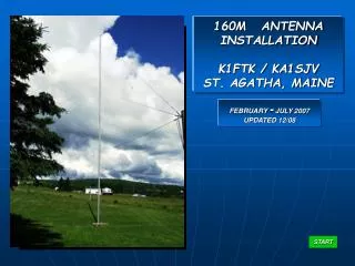
160M ANTENNA INSTALLATION K1FTK / KA1SJV ST. AGATHA, MAINE FEBRUARY - JULY 2007 UPDATED 12/08 START
-- BACKGROUND -- February 2007 After getting the bug to operate 160m in the winter of 2006, we installed one of the commercially available 160 meter vertical antennas just in time for the 2006 CQ WW 160 contest. This antenna required no guys or radials and claimed to be “ground independent”. At that time our ground was solidly frozen and, with ~4’ of snow down, it was really our only option. The antenna worked when the band was open, but otherwise, not very well. It also had a very poor S/N ratio. In the Fall 2006 we moved and raised the antenna to a better location away from the house / garage and their metal roofs. Performance did improve for the 2007 CQ WW 160 contest, but still, it was nothing to brag about. It had to be replaced. As a side note; We later found that our local ground condition is bad (heavy shale) .. this more than likely contributed to “some”, but not all, of the antenna’s inefficiency. We looked at other various commercialdipoles and verticals. They too, had questionable efficiencies … they were short, had loading coils, meant to be mounted low or they had unsupported counterpoise arms which are not good in our ice storms etc. NEXT BACK
March 2007 In the late Winter of 2007 we talked with Dave Bowker, K1FK, in Ft. Kent to get an idea of what he thought might be a good solution. Dave had previously constructed a 75’ 160 / 80m vertical at his QTH in 1999. Details of the main element construction can be found in either ARRL publication; “QST” June ’04 “More Vertical Antenna Classics” After a lot of discussion and modeling, Dave designed a modified version for a dedicated 160m 60’ vertical antenna with 4 - 55’ long top loading wires and 60- 60’ radials. Our target center frequency was 1.860 MHz with a 2:1 bandwidth of ~80KHz . 1.860 MHz Early plot indicating ~30º take-off angle and good null at the zenith NEXT BACK
March 2007 One problem that had to be dealt with during the modeling was the local ground condition, it’s very poor due to the heavy shale deposits. ----- Published data shows our “typical” local ground conditions as ----- Bad Ground > Conductivity of 1 mS/m Dielectric constant of 3 Where As ( Ref: NEC4WIN ) : Poor Ground > Conductivity of 2 mS/m Dielectric Constant of 12 Medium Ground > Conductivity of 5 mS/m Dielectric Constant of 13 Good Ground > Conductivity of 6 mS/m Dielectric Constant of 14 Excellent Ground > Conductivity of 30 mS/m Dielectric Constant of 20 1” Polyethylene pipe used for the coax run Our typical ground condition BACK NEXT
April 2007 The antenna’s vertical element and four guy posts were constructed from 30’ lengths of 5” diameter, .055” wall aluminum irrigation pipe. After cutting the steel couplers from the pipe ends, each resulting section only weighed 30 lbs. The vertical element consists of two 30’ sections joined together with a 4’ long internal doubler that was riveted in place. The element is guyed at 20’, 40’ and 60’ with the 60’ level containing the 55’ long top loading wires. May 2007, Installation began After the snow finally melted, we did the layout using a surveyor’s transit (we have a collection of 25 transits and levels dating from 1850-1960) to ensure that the guy posts where at 90º , centered on the antenna pier and that the actual guy points were at the same elevation. Each guy point elevation was critical in order to maintain a uniform top loading wire angle, which in our case is 39 ½ º. This gave us a take-off angle of ~30º. . . . . Our final guy point heights’ were designed to be . . . . West 7’, North 14 ½’, East 9 ½’ and the South 8 ½’. BACK NEXT
THE INITIAL ANTENNA LAYOUT . . . This was based on our land survey that was done in 2005 It fits perfectly in the availablespace BACK NEXT
TYPICAL GUY LINE AND TOP LOADING WIRE DETAIL 14ga Copperweld Top Loading Wire 3/16” Double Braided UV Resistant Dacron guy lines GUY POST DESIGN REQUIREMENTS Maintain a uniform top loading wire angle of 39 1/2º Tractor cab clearance of 7’ under the West lower guy line. BACK NEXT
--- GUY POST INSTALLATION --- After all the guy post locations were double checked against the layout, 8” diameter holes were bored and the forms placed. Each guy post was then set in ~400 lbs of 4000 psiconcrete, plumbed and left to cure. Ex: East guy post Ex: North guy post BACK NEXT
--- OVERVIEW OF THE COMPLETED GUY POSTS --- East, South and West posts West, North and East posts BACK NEXT
After the guy posts were installed, a 1924 Buff & Buff transit was aligned to the antenna pier and all guy point elevations were double checked. This was required before drilling and installing the guy post eyebolts. They had to be in the same plane . . Ex: Checking the South guy point elevation . . . . Ex: Checking the West guy point elevation . . . . BACK NEXT
Ground preparation for the first 10 of 60 radials began by cutting the grass as low as possible . . . . Then, using an electric edger with a 7 ½ “ diameter, serrated steel blade, grooves were cut to a depth of ~1 ¼”. Following that, each of the 14ga copper wires were embedded. Natural erosion and grass will eventually fill the grooves. BACK NEXT
--- PREPARATION FOR INSTALLING AND BONDING THE RADIALS --- K1FTK shown cutting the grooves for the radials KA1SJV shown embedding the radials K1FK radial bonding clamp made from ¾” copper pipe Groove BACK NEXT
--- RADIAL PREPARATION AND BONDING TECHNIQUE --- K1FK shown stripping the radials in preparation for silver soldering to the bonding clamp Radial bundle soldered to the bonding clamp and now secured to an 8’ ground rod BACK NEXT
--- ANTENNA RAISING SEQUENCE --- 60’ Antenna 30’ Derrick We’re now ready to hand raise the derrick . . . BACK NEXT
KA1SJV PIC K1FTK K1FK With the derrick fully raised, K1FTK secured the intermediate South guy points from the derrick to the antenna at the 20’ and 40’ levels in preparation for the raising. The intermediate guy points will be removed once the antenna is raised. BACK NEXT
KA1SJV PIC K1FTK K1FK The derrick being hand lowered by K1FK, the antenna is now at ~45º. K1FTK keeping light tension on the top loading wires to prevent them from developing kinks. BACK NEXT
Derrick now fully lowered and the antenna is at 90º With the antenna fully raised, all guy lines are secured to their respective posts so the derrick can be removed. K1FK BACK NEXT
--- K1FK BASE INSULATOR --- The lower stud will thread into the antenna pier Once installed on the pier, the antenna will set in the top groove similar to above BACK NEXT
--- K1FK RFMATCHING TRANSFORMER --- The bifilar winding on this ferrite rod produces a perfect 25 transmission line required for the low impedance 1:4 RFMatching Transformer. Loss at 1.8 MHz, <0.05 dB BACK NEXT
3/16” Wide Spark Gap With the raising fixture and derrick now removed and all guys fully secured . . The base insulator, spark gap, ground strap, feed strap, coax and matching transformer box were installed . . BACK NEXT
--- THE COMPLETED ANTENNA --- • THIS WAS A MAJOR PROJECT; MADE • POSSIBLE THROUGH THE EFFORTS OF: • K1FK , ANTENNA ENGINEERING • RF MATCHING TRANSFORMER • BASE INSULATOR • ( A VERY SPECIAL THANKS ! ) • KA1SJV, EMBEDDING 3600’ OF RADIALS • GUY POST INSTALLATION • ELEMENT CONSTRUCTION • SITE LAYOUT • K1FTK, GUY POST DESIGN • GUY POST INSTALLATION CUTTING RADIAL GROOVES • ELEMENT CONSTRUCTION • SITE LAYOUT • IT WAS FUN AND VERY EDUCATIONAL! N7GLR PIC K1FTK BACK NEXT ( NICE LIGHTNING ROD ! )
--- INITIAL TESTING AND FIRST ON AIR RESULTS, JUNE / JULY 2007 --- • ANTENNA IMPEDANCE • Freq = 1.890 MHz Z = 12.5 +/-j0 • Freq = 1.860 MHz Z = 10 +/-j0 • Freq = 1.830 MHz Z = 11 +/-j0 • Resonance at 1.860 MHz SWR 3.9 SIGNAL STRENGTH AT N7GLR (Compared to 2006, nominal600W) An increase of ~ + 3 ½ S units (22dB) ( Based on Kenwood TS50 6 dB / S unit ) IMPEDANCE MATCHING RESULTS The low impedance1:4 RF Matching Transformer lowered the SWR to 1.0 : 1 @ 1.849 with a 2:1 bandwidth of ~80 KHz This also provides ground for static discharge. • EQUIPMENT USED FOR IMPEDANCE MEASUREMENTS • AEA CIA-HF Analyzer (K1FK) • PALSTAR ZM30 Digital Antenna Z Bridge (K1FTK) BACK NEXT
1.884 1.804 1.849 SWR PLOT 1.0 : 1 @ 1.849 MHz PALSTAR ZM30 Digital Antenna Z Bridge BACK BACK NEXT NEXT
UPDATE …. 12/08 2008 CQ160 SSB CONTEST RESULTS (UNDER MY OLD CALL WB1FTK) 1st PLACE FOR THE STATE OF MAINE 21,609 POINTS BACK BACK NEXT NEXT
’73 K1FTK KA1SJV BACK REPEAT