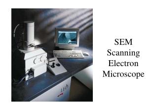
Scanning Electron Microscope (SEM)
Learn about SEM major components, operation principles, vacuum system, electron beam generation, manipulation, specimen interaction, detection, signal processing, and more. Explore videos and detailed information on SEM functioning.

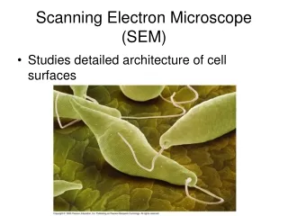
Scanning Electron Microscope (SEM)
E N D
Presentation Transcript
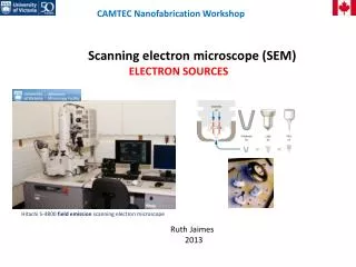
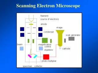
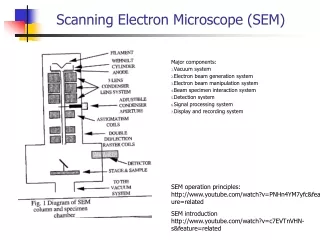
Scanning Electron Microscope (SEM) Major components: Vacuum system Electron beam generation system Electron beam manipulation system Beam specimen interaction system Detection system Signal processing system Display and recording system SEM operation principles: http://www.youtube.com/watch?v=PNHn4YM7yfc&feature=related SEM introduction http://www.youtube.com/watch?v=c7EVTnVHN-s&feature=related
Vacuum system Low vacuum pump (<10-3 Torr) (remove 99.99% of air), high vacuum pump(>10-3 Torr) SEM operation need 10-4 to 10-6 Torr
E beam generation • Three components: • 1) cathode (filament or field emission) • 2) grid cap that control the flow of electrons • 3) anode that attracts and accelerates electrons • Voltage ranges from 0.1 to 40 Kv, (10kV the most common for biological specimen) • the higher the voltage the better the resoution (but • greater heat will be generated on the specimen) • On/off switch for high voltage (HV) • Beam current (the flow of electrons that hit a sample), controlled by bias voltage between filament and grip cap, • Increasing beam current results in deeper penetration of electron and a larger diameter spot) • Filament current control (adjustment of current filament, providing necessary heating current to filament) • Filed emission: • advantages: cool cathode, emitted beam is smaller in diameter (better resolution), longer life time • disadvantages: higher vacuum need (~10-7 Torr), cleaner microscope needed, not many x-rays generated (due to low beam currents and small beam diameters)
E beam manipulation E-gun is controlled by electrostatic field, while the rest of SEM is controlled by magnetic lenses. Electromagnetic lenses: - condenser lenses: reduce spot size spherical aberration limit resolution - correct astigmatism (non-circular beam spot), due to beam formed by filament is elliptical, dirt in column, beam distorted on the aperture using stigmator (control strength and azimuth) - correct alignment - two sets of magnetic coils (raster coils) that move the seam scanning in the X and Y direction - magnification: ratio of dimension of CRT to dimension of the area being scanned two ways of magnification adjustments: 1) change scanned area of the specimen 2) adjust focal point of the beam and working distance (move Z-axis to bring sample to focal point) Aperture: a round hole that control the passing through of scattered electrons - small aperture for high resolution - big aperture for low resolution with more electrons needed
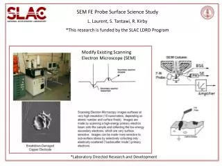
Beam interaction Backscattered electrons: original beam electrons, high energy level, useful when relative atomic density information with topographical information is displayed Secondary electrons: generated by dislodging specimen e or other secondary e a few eV, detected near the surface, can obtain topographical and high solution, contrast and soft shadows of image resemble specimen illuminated with light X-rays: can obtain elemental information (from wavelength and energy characteristic of elements) measurement of wavelength (wavelength dispersive spectrometer (WDS)) or energy level (energy dispersive spectrometer (EDS)) wavelength range: 10 ~ 0.01 nm (3x10¹⁶ ~ 3x10¹⁹ Hz), soft x-ray:0.12ev~12 keV, hard x-ray:12kev~120 keV, http://www.lbl.gov/MicroWorlds/ALSTool/EMSpec/EMSpec2.html http://www.physics.isu.edu/radinf/xray.htm
Cathode Luminescence: • specimen molecule’s florescence that produces light photon Specimen current: • e energy decreases after scattering and e absorbed by sample • can build up negative charge and lead to charging Transmitted electrons: • primary e pass through specimen • provide atomic density information displayed as a shadow higher the atomic number the darker the shadow
Review for SEM Operation • Contamination : image become dark when irradiated on a portion for a long time, cause by residual gas being struck by e. probe (see the guide on p.17) • Charge-up: negative charge collected that leads to prevent normal emission of second e.
Signal Detection Detector Structure • secondary e. attracted by 200V applied to ring around the detector (Faraday Cup) • e. accelerated by 10 Kv applied to hit scintillator and produce photons • photons travel down to photomultiplier (PM) where signal is increased or amplified (PM control contrast) Topological Features • density of emissive area determine signal strength • emissive area affected by topology such as flatness, pointed structure, edge (see the guide on p. 9) X-ray detection • x-ray loss energy by hitting another particles that produce background • EDS detector gather spectrum from 0 to 30 ev • WDS is set to detect a small a range (more sensitive than EDS)
Signal Manipulation • brightness and contrast are main control of signal manipulation • brightness: actual value of each pixel control by adding or subtracting value for each pixel • contrast: difference between two pixels control by the amplifier of secondary e. (PM)
Display and Record System • Brightness • Contrast • Resolution: ability to distinguish between two points determined factors: beam spot size, working distance, aperture size, beam bias current/voltage, how cylindrical the beam is • Magnification: a function of area scanned and viewing size adjusted by raster coils and location of focal point of the primary beam to final lens • Depth of field: region of acceptable sharpness in front of and behind focus points • Noise: can be controlled by increasing signal (aperture size, bias voltage, etc) decrease noise increasing scanned time
Waveform Monitor used to set appropriate brightness and contrast