Scanning Electron Microscope
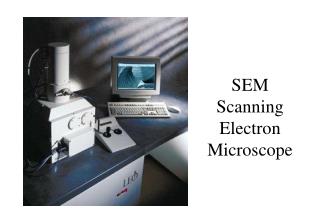
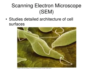
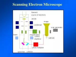
Scanning Electron Microscope. The basic premise of an SEM is that signal produced from a scanned area of the specimen is displayed as an image with the exact same scan pattern on a CRT.

Scanning Electron Microscope
E N D
Presentation Transcript
The basic premise of an SEM is that signal produced from a scanned area of the specimen is displayed as an image with the exact same scan pattern on a CRT
The scan pattern on the specimen is created by a set of deflection coils in the column that move the beam in a coordinated X/Y pattern. This is referred to as a scan or “raster” pattern
Cathode Ray Tubeaccelerates electrons towards the phosphor coated screen where they produce flashes of light upon hitting the phosphor. Deflection coils create a scan pattern forming an image in a point by point manner
Color CRTs usually have three separate e-guns, one each for red, green, and blue (RGB)
The scan generator coordinates the movement of the primary beam with the movement of the e-gun in the back of the CRT
Magnification is accomplished by scanning a progressively smaller portion of the specimen and displaying the image on the CRT. Thus total magnification is square area of CRT divided by area scanned.
In contrast focus is accomplished by bringing the beam to its crossover point on the surface of the specimen. In this way focus and magnification are completely separate from one another in the SEM.
In the TEM the specimen lies very close to the objective lens resulting in a relatively large half angle of illumination. In SEM since the image is not formed by an objective lens the half angle can be very small resulting in a large depth of field.
10X An SEM focused at high magnification will still be in focus at low magnification
Weak Lens: Larger probe size, low resolution, long working distance, and larger depth of field Strong Lens: Small probe size, high resolution, short working distance and shallow depth of field
A smaller final lens aperture can reduce the half angle and therefore increase the depth of field. This is true on a relatively strong lens which has a fairly short working distance and therefore high resolution.
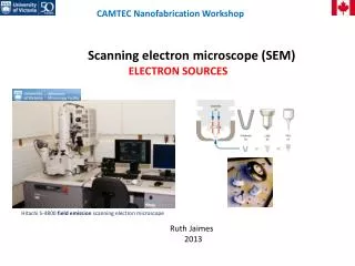
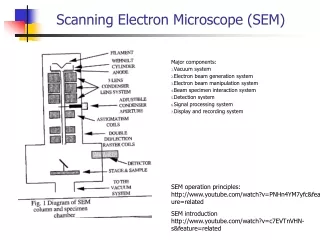
The SEM forms an image by generating a number of signals as a result of the beam interacting with the specimen.
The SEM is a probe forming (e- beam) and signal detecting device. By developing an image created in a point by point fashion an important factor is the signal to noise (S/N) ratio. The signal being the result of the beam interacting with the specimen and the noise being the result of imperfections in the electronics of the detector and display systems as well as spurious signal.
Signal can be increased by: Creating more beam specimen interactions Noise can be reduced by: Cooling electronics Keeping detectors settings to a minimum Signal/noise ratio can be increased by: Placing detector closer to source of signal Slowing down the scan (collect more signal per unit time)
Although the same amount of signal is produced throughout the specimen the topography of the surface will allow differing amounts of signal to reach a detector placed off to the side.
A number of different detectors can be incorporated into the chamber surrounding the specimen.
The shadow produced in an SEM is determined by the position of the detector but the view is a “beam’s eye” view as if column one were looking down the
LEO Gemini Column A detector placed within the column is known as an “in-lens” detector and produces a very different image compared to a conventionally located detector
Secondary Electron Detector Side Mounted In-Lens
Secondary Electron Detector Side Mounted In-Lens