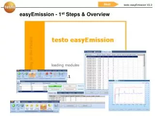
EasyEmission - 1st Steps & Overview
Go straight to the tasks you want to do with easyEmission! Click on the field to open the chapters for Getting Started, Advanced, Connect analyzer/PC, Realtime measurement, Testo-Bus connection, and more. Start using easyEmission today!

EasyEmission - 1st Steps & Overview
E N D
Presentation Transcript
Go straight to the tasks you want to do with easyEmission! Just CLICK on the field to open the chapters! Getting Started… Advanced… Connect analyzer / PC Using more than one analyzer Serial connection Setup system Bluetooth® 2.0 Realtime measurement Testo-Bus connection Import Testo templates Create NEW folders & locations Create reports for customized printouts Download measurements from the analyzer Measure types and related functions First real time measurement Analyze your measurements Export data Change instrument settings Print out measurements Export to other programs Export easyEmission files
Connect analyzer with easyEmission Serial Connection Start
Connect Analyzer – PC • Connection via serial interface • Serial connection is set up using a testo 350 Control Unit. Only one Control Unit can be connected to the measurement system! • For serial connection of testo 350 to a PC, the “PC connection cable/0409 0178 instrument” is required. • Cable connection • Connect connection cable to a serial connection socket in the PC • Connect connection cable to the RS232 socket of the ControlUnit • Switch on measuring instrument Computer Analyzers
Connect Analyzer – PC • Connection via serial interface • The measuring instrument switches to the Slave Mode while data is being exchanged, the control buttons in the measuring instrument are blocked in this mode. If data is not being exchanged, the Slave Mode is stopped and the measuring instrument can be controlled normally via control buttons. • If the connection is interrupted without stopping the software, testo 350 remains in Slave Mode. • Do the following to deactivate • Slave Mode:
Connect analyzer to easyEmission Bluetooth connection Start
testo Bluetooth connection • Plug in the analyzerbox without Control Unit • Use your specific Bluetooth®2.0 program on your computer and search / connect the testo 350-S/-XL analyzer with your computer add the analyzer as a new device the Bluetooth Security Code is 1234 (default) pair the analyzer • Check which “virtual” serial comport is used for the analyzer-Bluetooth connection • Start easyEmission Connect the analyzer with easyEmission
testo Bluetooth connection • Connection limits • The data transfer technology is only Bluetooth® 2.0 or higher • Operating distance (free field) max. 320 ft • Interference sources can impact the connection, e.g. high voltage sources, microwaves, cordless phones, electrical radio devices …
Connect analyzer with easyEmission testo data bus Start
Software easyEmission - Connection Connection via USB data bus controller • USB connection is set up directly to the flue gas analysers via the data bus controller. No Control Unit has to be connected to the measurement system! • The USB data bus controller is a High Power instrument, an additional USB Hub maybe required • Connecting the flue gas analyser to the data bus controller: Connect the instrument plug of the cable to the DATA socket of the testo 350 analyser box and connect the serial connection plug of the cable to the Channel 1 socket in data bus controller. • Connect the USB data bus controller to PC: Connect the USB plug (Type B)of the cable to the USB socket in data bus controller, connect the other USB plug (Type A) to a USB socket of the PC. • Connect the power plug with the analyser box • Start first the Program testo 350 CAN Controller and then easyEmission
Software easyEmission - Connection • Start first the program testo 350 CAN Controller (connection between CANCase and Computer) and then easyEmission
Create new folders and new locations Start
Create new folders / new locations • Insert Folder name TEST and • Insert a site name to specify a measurement site
Create new folders / new locations • Insert a site with the name Site One and • Use the flag folder and double-click on it … • … to see the site name “Site One” in this folder
Get your measurements from the analyzer to the computer Start
Get your measurements from the analyzer to the computer • Download measurement data • Shows you measurements which are only in the analyzer. Measurements in the analyzer Status: Not yet downloaded
Get your measurements from the analyzer to the computer • Download -> the data will be saved under the same folders like in the analyzer • Download as > Choose an existing folder / site in easyEmission to save your data in the marked folder
Get your measurements from the analyzer to the computer • After “Download as” -> the data is saved under existing folders in easyEmission • After “Download as” -> the data is saved under existing folders in easyEmission • You can now delete the data from the analyser
Real time measurement Start
Real time measurement • If needed choose out connection • Start measurement
Real time measurement • Instrument is zeroing first • Measurement starts • Readings in a 1 second cycle • you can change the cycle while measuring … test it! • Stop measurement
Analyze your measurements • Use the “measurement flag” with the “Search measurement” function • Double click on “Noname” folder
Analyze your measurements • Get information about the measurement and the used analyzer • Show the readings in a graph • Show the readings in a table
Print out measurement data • Open measurement data Double click …. … or mark the measurement and use the button
Printout measurement data • Print • Choose out one of the given report-templates e.g. “Online measurement” or “Flue gas measurement” both are default reports in easyEmission • Use your specific printer to print out the measurements
Export measurement data from easyEmission “Copy – Paste” / pdf Start
Export measurement data • Print out -> Print out your data with the given reports (use the Preview function to see how it looks like) • Save as PDF -> Choose out a report and save your data in a not-changeable document
Export measurement data • Save your measurements as an MS Excel-file
Export measurement easyEmission measurement files Start
Export easyEmission measurement files • Mark the desired measurement • Use the import / export function it will create a zip-file with all the measurement information and the data
Export easyEmission measurement files • Fill in a file-name and save it on your computer • To use this files DON’T unzip it • easyEmission can only work with the files in the .zip format
Using more than one analyzer testo data bus Start
testo data bus connection • Connect the instruments with the data bus cables Control Unit testo 350 XL or further testo 350 analyzer
testo data bus connection • Connect the instruments with the data bus cables • Ideally, connect the cables when the system is switched off. • Ensure that the individual components have different bus addresses • If not: Click the Control Unit (CU) on the analyzer Press OK for the menu choose out the analyzer Menu “Ops Info” set the bus address • Connection limits • Max. 50 m with power supply to the components through the databus • Several hundred metres without power supply to the components through • the databus (all analyzers in the system with own power supply) • When routing the cables, ensure that they are not laid beside three-phase power • or similar cables. This could impair the function
testo data bus connection – at a glance • Please use Testo data bus cables only. • When routing the cables, ensure that they are not laid beside three-phase power • or similar cables. This could impair the function! • Ideally, connect the cables when the system is switched off. So-called “Hot-Plugging” is possible, although is may be necessary to switch the entire system off and on depending on the combination. • Ensure that the individual components have different bus addresses (BUS ID) • The maximum cable length from the first to last bus subscriber is 3000 ft • The data connection is linear in structure. The beginning of the line is the Control Unit. The terminal plug must be used for the loggers at the last instrument on the data bus.This ensures a defined electrical state.
Set up the data bus connection with easyEmission • See all bus subscribers in the overview • Change different settings e.g. change the device identifier for the subscribers in the system
Real time measurement with instrument groups Start
Real time measurement with instrument groups • Set measure type • Set instrument group • Set measurement cycle • Startmeasurement • See the readings, signed with the analyzer bus address e.g. % O2 (10) from analyzer with the bus address 10
Real time measurement with instrument groups • If you don’t want to see all readings set the instrument group e.g. only NOx readings
Save real time readings Start
Save real time readings “Copy” & Paste: Transfer all readings into the buffer memory and paste it into other programs. Click Clipboard -> past in the other program • Save your readings in easyEmission
Parallel Sessions Use more than one window Start
Use more than one window – Parallel sessions • Use different session with different settings and save / store it in different measurements • Change the number of parallel sessions
Use more than one window – Parallel sessions • You can switch between the windows while the online-measurement • Use different settings for the different windows (see red arrows) • Use different session with different settings and save / store it in different measurements
Manage Instrument Groups Start
Manage instrument groups easyEmission • Several flue gas analysers can be pooled to form an instrument group for online measurements. Each instrument or individual measurement channels in the instrument can then be allocated to several • instrument groups. • Define a new instrument group e.g. NOx readings
Manage instrument groups easyEmission • Activate measurement channels of all instruments or certain instruments or deactivate