Download
1 / 206
2.13k likes | 2.44k Vues
11. FUEL OIL SYSTEM FUEL INJECTION EQUIPMENT. Part I.

E N D
11 FUEL OIL SYSTEM FUEL INJECTION EQUIPMENT B. Pritchard, J. Luzer, M. Borucinsky, A. Spinčić
Part I. B. Pritchard, J. Luzer, M. Borucinsky, A. Spinčić
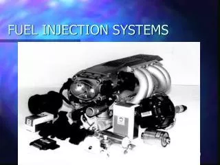
The function of the fuel injection system is to provide the right amount of fuel at the right moment and a suitable condition for the combustion process. There must therefore be some form of metered supply, a means of timing the delivery, of atomisation and distribution of fuel. • There are two basic system in use. One is the common rail system, in which a single pump supplies fuel at high pressure to a common manifold feeding the cylinders. Injection of the fuel to each cylinder takes place through a fuel valve operated from the camshaft which releases a metered amount of fuel into each cylinder at the instant it is required. B. Pritchard, J. Luzer, M. Borucinsky, A. Spinčić
Supply the missing text • The function of the fuel injection system is to provide the right amount of fuel ................... and a suitable condition for the combustion process. There must therefore be some form of metered supply, a means .................., of atomisation and distribution of fuel. • There are two basic system in use. One is the .........................., in which a single pump supplies fuel at high pressure to a common manifold feeding the cylinders. Injection of the fuel to each cylinder ................... through a fuel valve operated from the camshaft which releases a metered amount of fuel into each cylinder ........................... it is required. B. Pritchard, J. Luzer, M. Borucinsky, A. Spinčić
The other system is known as the jerk pump system, in which the fuel is metered and raised in pressure by a separate fuel pump for each cylinder. The pump is timed to force the fuel through the injector into the cylinder at the appropriate moment. • The great majority of medium and slow speed engines use the latter system. Fig.11.1. shows a jerk type fuel pump. B. Pritchard, J. Luzer, M. Borucinsky, A. Spinčić
Supply the right term • The other system is known as _____________, in which the fuel is metered and raised in pressure by a separate ____________ for each cylinder. The pump is timed to force the fuel through the _______________ into the cylinder at the appropriate moment. • The great majority of medium and _______________ engines use the latter system. Fig.11.1. shows a __________ type fuel pump. B. Pritchard, J. Luzer, M. Borucinsky, A. Spinčić
The plunger is actuated by a cam and a roller follower. A helical spring is fitted to return the plunger on its down stroke and to maintain contact of follower on the cam. • When the follower is on the base circle of the cam, the pump plunger is at the bottom of its stroke and the inlet port in the barrel is uncovered allowing the fuel to fill that portion of the barrel above the plunger. • The plunger is a close fit within a barrel. As the cam rotates the plunger rises and seals off the inlet and relief ports and at this point of the stroke the pumping action starts./ See Fig.11.2.(a). B. Pritchard, J. Luzer, M. Borucinsky, A. Spinčić
Supply the missing part of the sentences below • The plunger ....................... a cam and a roller follower. • A helical spring ................ to return the plunger on its down stroke and to maintain contact of follower on the cam. • When the follower is on the base circle of the cam, the pump plunger is ......................... and the inlet port in the barrel is uncovered allowing the fuel to fill that portion of the barrel above the plunger. • The plunger is ..................... within a barrel. • As the cam rotates the plunger rises and seals off the inlet and relief ports and ............................. the pumping action starts. B. Pritchard, J. Luzer, M. Borucinsky, A. Spinčić
Further upward movement of the plunger causes the fuel to be raised in pressure and expelled through the delivery valve to the injector. A helical groove (or helix) extends from the top of the plunger part way down its cylindrical surface. • When the edge of the helix uncoveres the relief port, the high pressure in the fuel above the plunger is released and pumping ceases / See Fig.11.2.(b)/, altough the plunger continues to move upwards. • The amount of fuel delivered will vary in accordance with the effective length of the stroke. This is controlled by rotating the plunger in the barrel by means of rack and pinion, the latter being machined on the outside of a sleeve . The sleeve fits over the plunger engaging it with keys.(Fig.11.3.) The rack position, therefore, determines the quatity of fuel supplied. B. Pritchard, J. Luzer, M. Borucinsky, A. Spinčić
Supply the missing terms • Further upward movement of the p__________ causes the fuel to be raised in pressure and expelled through the d______ _____ to the injector. • A helical groove (or __________ ) e___________ from the top of the plunger part way down its cylindrical surface. • When the edge of the helix uncoveres the r______ _____ , the high pressure in the fuel above the plunger is released and pumping c__________ , although the p__________ continues to move upwards. • The amount of fuel d___________ will vary in accordance with the effective length of the stroke. • This is controlled by rotating the plunger in the b___________ by means of r__________ and pinion, the latter being machined on the outside of a sleeve. • The s___________ fits over the plunger engaging it with k___________ . • The rack position, therefore, determines the quatity of f___________ supplied. B. Pritchard, J. Luzer, M. Borucinsky, A. Spinčić
Supply the missing terms • Further upward movement of the ___________ causes the fuel to be raised in pressure and expelled through the ___________ to the injector. • A helical groove (or ___________ ) ___________ from the top of the plunger part way down its cylindrical surface. • When the edge of the helix uncoveres the ___________ , the high pressure in the fuel above the plunger is released and pumping ___________ , altough the ___________ continues to move upwards. • The amount of fuel ___________ will vary in accordance with the effective length of the stroke. • This is controlled by rotating the plunger in the ___________ by means of ___________ and pinion, the latter being machined on the outside of a sleeve. • The ___________ fits over the plunger engaging it with ___________ . • The rack position, therefore, determines the quatity of ___________ supplied. B. Pritchard, J. Luzer, M. Borucinsky, A. Spinčić
The timing of the injection is controlled by the instant that the pump plunger closes the inlet and relief ports. This instant can be adjusted with the reference to the camshaft and crankshaft position by raising or lowering the plunger by the screw in the tappet shown in Fig.11.4. Raising the level of the screw will advance the point of injection. • After leaving the pump delivery valve, the fuel is conveyed by high pressure steel piping to the injector. The fuel flows at high velocity through small holes in the injector nozzle causing it to divide up into fine spray which penetrates throughout the combustion chamber. • The high pressure of the fuel necessary to do this must be created sharply at the commencement of injection and must be just as sharply dropped when the injection ceases in order to avoid dribbling. B. Pritchard, J. Luzer, M. Borucinsky, A. Spinčić
Supply the missing text • The timing of the injection is controlled by the instant that the pump plunger ...................... • This instant can be adjusted with the reference to the camshaft and crankshaft position by ...................... by the screw in the tappet shown in Fig.11.4. • Raising the level of the screw will .......................... . • After .............................., the fuel is conveyed by high pressure steel piping to the injector. • The fuel flows at high velocity through small holes in the injector nozzle causing it ..................... which penetrates throughout the combustion chamber. • The high pressure of the fuel necessary to do this must be created sharply ............................ and must be just as sharply dropped when ..................... in order to avoid dribbling. B. Pritchard, J. Luzer, M. Borucinsky, A. Spinčić
QUESTIONS AND DISCUSSION • What does the fuel injection equipment provide ? • Mention the kinds of injection system ussually employed. • What is the main characteristic of the common rail fuel injection system ? • How is fuel injected in this system ? • In what does the jerk pump system differ from the common rail system ? • Which of the two systems of fuel injection is used to a greater extent today ? • Why is arack and a pinion device fitted to the jerk pump ? • What is the function of the delivery valve ? • Why is it a non-return valve ? • Why is the injector nozzle one of the most important component of the fuel injection system ? • What is the function of the needle valve ? • Why must the injector, particularly the nozzle and the needle, be inspected and serviced regularly ? • What is dribbling ? How is it prevented ? B. Pritchard, J. Luzer, M. Borucinsky, A. Spinčić
I. Label the Fig.11.5 and describe briefly the function of each component show in the diagram II Describe the operation principle of the jerk pump illustrated in Fig.11.6. in the stages (A), (B) and (C), following the headlines: • Position of plunger and helical groove relative to ports • Actuation of plunger • Result of plunger motion • Flow of fuel (see thicker arrows) B. Pritchard, J. Luzer, M. Borucinsky, A. Spinčić
III . The terms listed below summarize the main function of the fuel injection equipment. Define the meaning of each. • Metering • Timing • Atomisation • Distribution B. Pritchard, J. Luzer, M. Borucinsky, A. Spinčić
IV. State how: • metering is controlled • timing is adjusted • atomisation and distribution are ahieved B. Pritchard, J. Luzer, M. Borucinsky, A. Spinčić
V. State which of the statements given below are TRUE and which are FALSE. If FALSE, state why. • In the common rail system a separate injector pump serves each cylinder. • The jerk pump system is also known as the individual-pump injection system as the bulk of the job is carried out by the pump itself, which raises pressure, meters the charge and times the injection. • The term “helix” refers to the helical spring fitted in the barrel to return the plunger on its down stroke. • The timing of the injection can be altered by raising or lowering the pump plunger in relation to the cam. • Timing is adjusted by rotating the plunger in the barrel by means of a rack and pinion. • Atomisation is the usual term to indicate the proper distribution and penetration of fuel in the combustion chamber. • In all injection fuel pumps of the jerk type the plungers and barrels are so accurately fitted that no packing of any king is used. • The barrel and plunger of the injector pump are interchangeable: if a plunger or cylinder is worn out or damaged each may be easily replaced. • When the pump plunger releases the pressure in the barrel both the needle valve in the nozzle and the delivery valve snap back on to their seats to prevent dribbling. B. Pritchard, J. Luzer, M. Borucinsky, A. Spinčić
VREMENSKE REČENICE (Time Clauses) I • When the follower is on the base circle of the cam, the pump plunger is at the bottom of its stroke. • As the cam rotates the plunger raises and seals off the inlet port. • When the port is opened to the groove, the high pressure in the fuel above the plunger is released and pumping ceases. • Istaknutim rečenicama izraženo je vrijeme zbivanja radnje. Vremenske rečenice se uvode veznicima when (kada) i as (dok). B. Pritchard, J. Luzer, M. Borucinsky, A. Spinčić
Evo još nekoliko primjera vremenskih rečenica: • The followers are fitted clear of the cams, whilst they are moved axially. • Once the valve is open, the pressure of the exhaust gases assists in expelling them through the open valve. • One section of the duplex filter can be cleaned while the engine continues to run. • Portable extinguishers can contain a fire before it escalates. • After the fuel leaves the pump delivery valve, it is conveyed to the injector B. Pritchard, J. Luzer, M. Borucinsky, A. Spinčić
Ove su rečenice uvedene veznicima whilst, while(dok, za vrijeme dok), once (kada, jednom kada), before (prije, prije nego što) i after (nakon, nakon što). Pored tih još se upotrebljavaju: until (dok, dok ne), as soon as (čim), prior to (prije nego), when-ever(kadgod), as long as (dokle god, dok god). • Kada je glavna rečenica u sadašnjosti ili budućem vremenu, vremenska rečenica je u prezentu što se vidi iz rečenica 1-8. Treba znati da u engleskom jeziku iza vremenskih rečenica nikad ne dolazi futur. Prezentu vremenske rečenice u engleskom odgovara oblik prezenta ili futur drugi, npr: B. Pritchard, J. Luzer, M. Borucinsky, A. Spinčić
The chief engineer will examine the Engine Log when he has time. • Upravitelj stroja će pregledati Dnevnik stroja kada bude imao vremena. • (Futur II) • (10) Before the ship arrives into port, please advise the Engineer Superintendent. • Prije nego što brod stigne (ili “bude stigao”) u luku, molim da obavijestiš • Strojarskog inspektora. • (11) We shan’t be able to leave port until the bunkering is fully completed. • Nećemo moći isploviti dok potpuno ne završimo krcanje goriva. • (12) As soon as the temperature reaches the top value, stop the power supply. • Čim temperatura dosegne gornju granicu, isključi struju. (ili “ čim temperatura bude • dosegla …”). B. Pritchard, J. Luzer, M. Borucinsky, A. Spinčić
I. Join the following sentences by using the time links in brackets: (after, as, as soon as, before, until, when, while) Ex. The exhaust valve seat rings have worn out. They must be reconditioned by grinding. • When the exhaust valve seat rings have worn out they must be reconditioned by grinding. • The oil enters the cylinders. Impurities are extracted from the oil passing it through a filter. • The Third Engineer was at dinner. The supply pipe to the boiler burst. • Don’t use the new lubricating oil. The filter elemnts is first changed. • The air flows through the diffuser. Its velocity falls and is converted into pressure. • I was leaving the engine room. I met the master. • The pressure of the exhaust gas is almost down to a minimum. It has passed through the turbine. • The crankshaft has to be handled outside the engine. It should be carefully supported. • The rotary vane of the spur wheel is turned together with the camshaft. The vanes come to rest against the stop segment. B. Pritchard, J. Luzer, M. Borucinsky, A. Spinčić
II. Join each pair of sentences by using the time link in brackets. Remember that the Future Tense is not used in Time Clauses, use the Present Tense instead. Ex. The ship will reach port. Its dangerous cargo will be unloaded. (as soon as) • As soon as the ship reaches port its dangerous cargo will be unloaded. • The cadet will take your letter to the Post Office. He will go ashore. (when) • The refrigerator will continue to make that noise. We shall repair it. (until) • New main beraings will be fitted. The ship will laeve port. (before) • The heavy fuel oil will be heated. It will be properly atomised. (when) • The lubricating oil pump will be assembled. The necessary spare part will come. (as soon as) • The rain will stop. We’ll go ashore. (when) • The mechanic will overhaul the crane winches. The ship will be at sea. (while) • The Superindendant will know the facts. He won’t express an opinion about the causes of engine breakdown. (until) B. Pritchard, J. Luzer, M. Borucinsky, A. Spinčić
III. Translate into English: • Gorivo se ubrizgava u cilindar čim se oslobodi odgovarajuća količina goriva. • Nakon što se podigne brijeg bregaste osovine tada počinje pumpanje goriva. • Prije nego što gorivo dođe do ubrizgivača ono se stlači putem klipa za gorivo. • Dok je izlazni otvor pumpe začepljen, prekinuta je dobava goriva u cilindar. • Kada gorivo pod velikim pritiskom dođe do sapnice ono se razdvaja u sitnu “prašinu” i ulazi u cilindar. B. Pritchard, J. Luzer, M. Borucinsky, A. Spinčić
Part II. B. Pritchard, J. Luzer, M. Borucinsky, A. Spinčić
FUEL OILS B. Pritchard, J. Luzer, M. Borucinsky, A. Spinčić
FUEL OILS • H.F.O. B. Pritchard, J. Luzer, M. Borucinsky, A. Spinčić
FUEL OILS • H.F.O. Heavy fuel oil( residual, blends & crudes ); B. Pritchard, J. Luzer, M. Borucinsky, A. Spinčić
FUEL OILS • H.F.O. Heavy fuel oil( residual, blends & crudes ); • D.F.O. B. Pritchard, J. Luzer, M. Borucinsky, A. Spinčić
FUEL OILS • H.F.O. Heavy fuel oil( residual, blends & crudes ); • D.F.O. Diesel fuel oilorM.D.O. Marine Diesel oilorlight fuel oil( in restricted sense ) B. Pritchard, J. Luzer, M. Borucinsky, A. Spinčić
FUEL OILS • H.F.O. Heavy fuel oil( residual, blends & crudes ); • D.F.O. Diesel fuel oilorM.D.O. Marine Diesel oilorlight fuel oil( in restricted sense ) • 1.1.1 Residuals B. Pritchard, J. Luzer, M. Borucinsky, A. Spinčić
FUEL OILS • H.F.O. Heavy fuel oil( residual, blends & crudes ); • D.F.O. Diesel fuel oilorM.D.O. Marine Diesel oilorlight fuel oil( in restricted sense ) • 1.1.1 Residuals are residues from various rafinery processes; B. Pritchard, J. Luzer, M. Borucinsky, A. Spinčić
FUEL OILS • H.F.O. Heavy fuel oil( residual, blends & crudes ); • D.F.O. Diesel fuel oilorM.D.O. Marine Diesel oilorlight fuel oil( in restricted sense ) • 1.1.1 Residuals are residues from various rafinery processes; • 1.1.2 Blends B. Pritchard, J. Luzer, M. Borucinsky, A. Spinčić
FUEL OILS • H.F.O. Heavy fuel oil( residual, blends & crudes ); • D.F.O. Diesel fuel oilorM.D.O. Marine Diesel oilorlight fuel oil( in restricted sense ) • 1.1.1 Residuals are residues from various rafinery processes; • 1.1.2 Blends are fuel oil mixtures of different viscosity to obtain a product of desired viscosity and density. B. Pritchard, J. Luzer, M. Borucinsky, A. Spinčić
FUEL OILS • H.F.O. Heavy fuel oil( residual, blends & crudes ); • D.F.O. Diesel fuel oilorM.D.O. Marine Diesel oilorlight fuel oil( in restricted sense ) • 1.1.1 Residuals are residues from various rafinery processes; • 1.1.2 Blends are fuel oil mixtures of different viscosity to obtain a product of desired viscosity and density. • 1.1.3 Crudes: B. Pritchard, J. Luzer, M. Borucinsky, A. Spinčić
FUEL OILS • H.F.O. Heavy fuel oil( residual, blends & crudes ); • D.F.O. Diesel fuel oilorM.D.O. Marine Diesel oilorlight fuel oil( in restricted sense ) • 1.1.1 Residuals are residues from various rafinery processes; • 1.1.2 Blends are fuel oil mixtures of different viscosity to obtain a product of desired viscosity and density. • 1.1.3 Crudes: natural mixtures consisting of hydrocarbons + sulphur, nitrogen and / or oxygen derivatives of hydrocarbons. B. Pritchard, J. Luzer, M. Borucinsky, A. Spinčić
FUEL OILS • H.F.O. Heavy fuel oil( residual, blends & crudes ); • D.F.O. Diesel fuel oilorM.D.O. Marine Diesel oilorlight fuel oil( in restricted sense ) • 1.1.1 Residuals are residues from various rafinery processes; • 1.1.2 Blends are fuel oil mixtures of different viscosity to obtain a product of desired viscosity and density. • 1.1.3 Crudes: natural mixtures consisting of hydrocarbons + sulphur, nitrogen and / or oxygen derivatives of hydrocarbons. 2. FUEL VISCOSITY B. Pritchard, J. Luzer, M. Borucinsky, A. Spinčić
FUEL OILS • H.F.O. Heavy fuel oil( residual, blends & crudes ); • D.F.O. Diesel fuel oilorM.D.O. Marine Diesel oilorlight fuel oil( in restricted sense ) • 1.1.1 Residuals are residues from various rafinery processes; • 1.1.2 Blends are fuel oil mixtures of different viscosity to obtain a product of desired viscosity and density. • 1.1.3 Crudes: natural mixtures consisting of hydrocarbons + sulphur, nitrogen and / or oxygen derivatives of hydrocarbons. 2. FUEL VISCOSITY Internal resistance of a fluid to relative movement. Oil is more viscous when cold. Viscosity is measuredin Redwood Universal, Saybolt Universal, Saybolt Furol and Engler, but most commonly in kinematic cSt. B. Pritchard, J. Luzer, M. Borucinsky, A. Spinčić
3. PURPOSE OF THE FUEL OIL SYSTEM B. Pritchard, J. Luzer, M. Borucinsky, A. Spinčić
3. PURPOSE OF THE FUEL OIL SYSTEM To store, transfer & clean the oil prior to injection. B. Pritchard, J. Luzer, M. Borucinsky, A. Spinčić
3. PURPOSE OF THE FUEL OIL SYSTEM To store, transfer & clean the oil prior to injection. 4. SEPARATE FUEL OIL SYSTEMS B. Pritchard, J. Luzer, M. Borucinsky, A. Spinčić
3. PURPOSE OF THE FUEL OIL SYSTEM To store, transfer & clean the oil prior to injection. 4. SEPARATE FUEL OIL SYSTEMS 4.1 H.F.O. B. Pritchard, J. Luzer, M. Borucinsky, A. Spinčić
3. PURPOSE OF THE FUEL OIL SYSTEM To store, transfer & clean the oil prior to injection. 4. SEPARATE FUEL OIL SYSTEMS 4.1 H.F.O. Heavy fuel oil → in navigation; B. Pritchard, J. Luzer, M. Borucinsky, A. Spinčić
3. PURPOSE OF THE FUEL OIL SYSTEM To store, transfer & clean the oil prior to injection. 4. SEPARATE FUEL OIL SYSTEMS 4.1 H.F.O. Heavy fuel oil → in navigation; 4.2 D.F.O. B. Pritchard, J. Luzer, M. Borucinsky, A. Spinčić
3. PURPOSE OF THE FUEL OIL SYSTEM To store, transfer & clean the oil prior to injection. 4. SEPARATE FUEL OIL SYSTEMS 4.1 H.F.O. Heavy fuel oil → in navigation; 4.2 D.F.O. Diesel fuel oil / or M.D.O. Marine Diesel oil / or light fuel oil→ in manuvering. B. Pritchard, J. Luzer, M. Borucinsky, A. Spinčić
5. FROM THE DOUBLE BOTTOM TO THE ENGINE B. Pritchard, J. Luzer, M. Borucinsky, A. Spinčić
5. FROM THE DOUBLE BOTTOM TO THE ENGINE 5.1 Oil is taken from the double bottom tanks and pumped into a settling tank. B. Pritchard, J. Luzer, M. Borucinsky, A. Spinčić
5. FROM THE DOUBLE BOTTOM TO THE ENGINE 5.1 Oil is taken from the double bottom tanks and pumped into a settling tank. 5.2 Then it is heated in the settling tank ( the sediment and the water are drawn off. ) B. Pritchard, J. Luzer, M. Borucinsky, A. Spinčić