Download
1 / 32
320 likes | 473 Vues
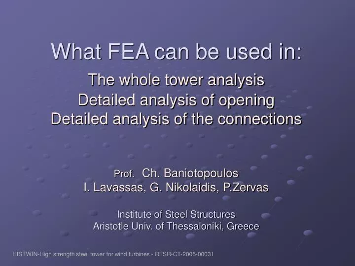
What FEA can be used in: The whole tower analysis Detailed analysis of opening Detailed analysis of the connections Prof. Ch. Baniotopoulos I. Lavassas, G. Nikolaidis, P.Zervas Institute of Steel Structures Aristotle Univ. of Thessaloniki, Greece.

E N D
What FEA can be used in:The whole tower analysis Detailed analysis of opening Detailed analysis of the connections Prof.Ch. BaniotopoulosI. Lavassas, G. Nikolaidis, P.ZervasInstitute of Steel StructuresAristotle Univ. of Thessaloniki, Greece HISTWIN-High strength steel tower for wind turbines - RFSR-CT-2005-00031
A wind turbine tower is a simple cantilever. Assuming uniform wind pressure along its height, moment & shear force at any point can be calculated directly regardless of the tower configuration Even when tower wind pressure is a function of height [ p=p(h) ] , moment & shear at the base can be calculated also by simple integrations of the load function Need for using a FE model HISTWIN-High strength steel tower for wind turbines - RFSR-CT-2005-00031
Meridional stress for local buckling check can also be easily calculated by hand Tower displacements & eigenmodes can’t be calculated so easily because of the change of the elastic characteristics of the cantilever along its height. For this calculation a computational model is needed Need for using a FE model HISTWIN-High strength steel tower for wind turbines - RFSR-CT-2005-00031
Computational model (Linear): All sections of the tower are simulated via linear beam elements. Rotor & blade system is simulated as a mass at the top of the tower placed with eccentricity Soil-structure interaction can be simulated by the use of a rotational spring at tower base By the use of a linear model we can calculate tower displacements and perform an eigenvalue analysis with accurate results. So what’s the need for a Finite Element model? Need for using a FE model HISTWIN-High strength steel tower for wind turbines - RFSR-CT-2005-00031
Cross section of the tower is deformed due to the wind loads Stress concentration at the door position cannot be estimated by a linear model Bolt forces at flange positions cannot be calculated from the linear model. A special FE model is needed. Anchor forces and the stress state of the concrete on anchoring position need to be determined. Soil-structure interaction affects the tower dynamic characteristics, and its displacements for wind loading. Need for using a FE model HISTWIN-High strength steel tower for wind turbines - RFSR-CT-2005-00031
Wind pressure distribution over the circumference of the tower causes ovalling of the circular tower section But when it comes to the positions where the tower section is much stiffer (flange & support positions) , the section shape is forced to be circular. This causes circumferencial stresses to the shell near flange positions In buckling check (EC 3-1-6) not only meridional stress but circumferencial & shear stresses are used in combination as well Need for using a FE model HISTWIN-High strength steel tower for wind turbines - RFSR-CT-2005-00031
A few years ago, developing of a complex Finite Element model was very difficult due to: Need of expensive big computers (and expensive software) to run a non-linear analysis Too much effort for developing the FE model geometry and loading Toο much effort by hand to interpret the results (stress integrations etc). Modern Finite Element software that can run on a simple PC offer: Direct input of the geometry from CAD software CAD capabilities inside the FEM software Geometrical & material non-linear analysis capabilities Unilateral contact with friction capabilities Non-linear analysis now can run on a personal computer Automatic procedures for results interpretation Interfaces to join with design software Modern Finite Element Software HISTWIN-High strength steel tower for wind turbines - RFSR-CT-2005-00031
Modelling Strategies can be described by the chart below: Overall model Modelling strategies Linear FE model Foundation Foundation included Separate model for the Foundation Foundation model Linear (grid on elastic support) FE model (including anchoring detail) Details (Flanges, Door position etc) : Finite Elements Separate models for the details Included to the general model • Three different strategies will be presented HISTWIN-High strength steel tower for wind turbines - RFSR-CT-2005-00031
1: Linear model for the tower, and analytical detailed FE models to the door and flange positions Modelling strategies 1:Linear model HISTWIN-High strength steel tower for wind turbines - RFSR-CT-2005-00031
FE model for the flanges and for the anchoring system Modelling strategies – 1:Linear model HISTWIN-High strength steel tower for wind turbines - RFSR-CT-2005-00031
Flanges are modelled using plate elements Bolts are placed as linear elements connecting the flanges active only in tension All other nodes are connected thru unilateral contact elements. Moment & shear force is applied distributed to the circumference. Modelling strategies – 1:Linear model HISTWIN-High strength steel tower for wind turbines - RFSR-CT-2005-00031
Advantages: Easy developing of the general model and the part models Fast calculation (on a simple PC: instant calculation for the overall model & 10-15 minutes for the non-linear models of the flanges) Easy change of the model configuration Disadvantages: Circumferencial variation of the tower loads cannot be introduced Boundary conditions for the part models need to be estimated Only meridional stress can be calculated Circumferencial & shear stresses are neglected EC 3-1-6 requires the complete stress-state (meridional, circumferencial & shear) for the buckling check Only Axial & Shear forces and Bending moment are available to be applied to the part models. In- plane deformation of the tower due to the wind load distribution is neglected Soil-structure interaction is neglected or need to be estimated by introducing a rotational spring on tower support Modelling strategies – 1:Linear model HISTWIN-High strength steel tower for wind turbines - RFSR-CT-2005-00031
Modelling the foundation by linear elements (grid of beams on unilateral elastic support) to simulate soil-structure interaction Modelling strategies – 1:Linear model • Simulates soil-structure interaction • Good for the design of the foundation • It doesn’t give an answer to the stress state of the anchoring system HISTWIN-High strength steel tower for wind turbines - RFSR-CT-2005-00031
Simple FE model for the tower, and corresponding analytical FE models to the door and flange positions Modelling strategies 2:Simple FE model HISTWIN-High strength steel tower for wind turbines - RFSR-CT-2005-00031
Advantages: Fast calculation in PC (about 1-2 minutes a run for the general model and about 10-15 minutes for the non-linear analysis of the flange models) Estimation of the full stress-state on any point Disadvantages: Boundary conditions for the part models need to be estimated Much effort is needed for the transfer by hand the stress-state of a specific cross-section to the corresponding cross-section of the part model. Soil-structure interaction is neglected or need to be estimated by introducing springs on tower support Modelling strategies - 2:Simple FE model HISTWIN-High strength steel tower for wind turbines - RFSR-CT-2005-00031
1: Complete detailed model for the tower and the foundation Shell skirts are modelled using shell elements Flanges are modelled using brick elements Foundation is modeled using brick elements Unilateral contact to the ground Modelling strategies - 3:Detailed FE model HISTWIN-High strength steel tower for wind turbines - RFSR-CT-2005-00031
Model details to the flange positions Modelling Strategies – 3: Detailed FE model Connection type for the flanges HISTWIN-High strength steel tower for wind turbines - RFSR-CT-2005-00031
Simulation of the eccentricity of mass at the top of the tower Top-flange is undeformed in-plane (rigid links connection). Modelling strategies – 3:Detailed FE model HISTWIN-High strength steel tower for wind turbines - RFSR-CT-2005-00031
Modelling strategies – 3: Detailed FE model Modelling of the tower- foundation anchoring • Embedded flange to the concrete • Partially prestressed anchors inside (but not connected to) the concrete • Unilateral contact between flanges & concrete Collapse due to anchoring system failure Nanamata, Japan HISTWIN-High strength steel tower for wind turbines - RFSR-CT-2005-00031
Modelling strategies – 3:Detailed FE model Foundation Modelling: • Concrete & shrink-mortar : Brick elements • Washer plates : Plate elements • Anchors : cable type elements active only in tension • Unilateral contact to the ground HISTWIN-High strength steel tower for wind turbines - RFSR-CT-2005-00031
Modelling strategies – 3:Detailed Fe model Cross-section to the foundation HISTWIN-High strength steel tower for wind turbines - RFSR-CT-2005-00031
Modelling strategies – 3:Detailed Fe model Anchoring Modelling detail • Each anchor is a single element connecting only the washer plates (active in tension) • Unilateral contact conditions between the base washer plate and the shrink mortar & between the embeded washer plate and the concrete HISTWIN-High strength steel tower for wind turbines - RFSR-CT-2005-00031
Modelling strategies – 3:Detailed Fe model Design of the foundation-anchoring system • Washer & base plates (von Mises stresses) • Prestressed anchors (tensile forces) • Non-shrink mortar (compressive & shear stresses) • Concrete (compressive,shear & punching shear stresses) • Reinforcing bars HISTWIN-High strength steel tower for wind turbines - RFSR-CT-2005-00031
Modelling strategies – 3:Detailed Fe model Reinforcing bars check points 1,2 : Footing, bottom mesh 3,4 : Footing, top mesh 5 : Top of pedestal mesh 6 : Pedestal vertical rebars (transfer of tensile anchor forces) 7 : Circumferencial reinforecement (split-up forces) HISTWIN-High strength steel tower for wind turbines - RFSR-CT-2005-00031
Advantages: Estimation of the full stress-state on any point Best possible approximation to the real-world situation No transfer of loads is needed from one model to another No need to estimate any partial model boundary conditions Disadvantages: Big effort for developing the FE model Changes to the model are difficult Non-linear calculation needs time to run on a personal computer (can take 4-5 hours a run on a modern PC) Modelling strategies - 3:Detailed FE model HISTWIN-High strength steel tower for wind turbines - RFSR-CT-2005-00031
Vertical loads Self mass & weight is estimated directly by the FE software The rotor & nacelle mass is applied to the top of the tower distributed to the nodes of the upper flange taking into account the eccentricity (mass instead of loads, to be used in spectrum analysis as well) Wind loads At the top of the tower, rotor forces and moments are applied At tower stem wind pressure is calculated acc. EC1-1-4 as a logarithmic function of z. Tower loads HISTWIN-High strength steel tower for wind turbines - RFSR-CT-2005-00031
Types of analysis for buckling check EC 3-1-6, LS3 (Buckling limit state): LA (Linear analysis) MNA & LBA (Material non-linear analysis & Linear buckling analysis) GMNIA (Geometric & material non-linear analysis with imperfections) Types of analysis HISTWIN-High strength steel tower for wind turbines - RFSR-CT-2005-00031
Seismic loading: Response spectrum analysis for the seismic loading must be performed Additional time history harmonic response analysis for the seismic loading (only in extreme cases) Due to the distributed mass of the tower itself two eigenmodes are participating.Equivalent lateral load method cannot be used Types of analysis HISTWIN-High strength steel tower for wind turbines - RFSR-CT-2005-00031
Comparison of results – Wind loading Tower displacements for the linear model vs FE models Linear model is accurate to the estimation of displacements for wind loading. HISTWIN-High strength steel tower for wind turbines - RFSR-CT-2005-00031
Comparison of the results – Eigenvalue analysis 1st & 3rd mode shapes for the three models HISTWIN-High strength steel tower for wind turbines - RFSR-CT-2005-00031
Comparison of results Comparison of the results for the three models HISTWIN-High strength steel tower for wind turbines - RFSR-CT-2005-00031
Conclusions: Although the use of an overall complex Finite Element model needs more calculation effort, it is necesary in order to establish a better approach the stress state on the structure With modern Finite Element software such a nonlinear analysis can be run on a simple personal computer The cost of developing such a model is extremely small compared with the budget of a single aeolic park installation Simplified models (linear model, even hand-calculation) are also necessary to develop in paralell, for initial design, and for checking the results of the FE model HISTWIN-High strength steel tower for wind turbines - RFSR-CT-2005-00031