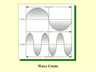
Wave Crests
Wave Crests. Heinrich Hertz. Speed of Light. Radio waves travel through space at a speed of approximately 300,000,000 meters per second. Electricity travels through a wire and light travels through fiber optics at a speed of approximately 200,000,000 meters per second. Electromagnetic Waves.
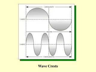

Wave Crests
E N D
Presentation Transcript
Speed of Light Radio waves travel through space at a speed of approximately 300,000,000 meters per second. Electricity travels through a wire and light travels through fiber optics at a speed of approximately 200,000,000 meters per second.
Traditional Classification of BandwidthsStill heard quite often, but less meaningful in today’s world.
Usually we talk directly in terms of actual Bands used. Microwaves Television & FM Radio AM Radio 802.11b & 802.11g Wireless LANs Visible Light & X-Rays
Calculating frequency and wavelength Example 1 A radio wave has a wavelength of 2 meters. Calculate the frequency in hertz. f = C l f (hertz) = 300,000,000 (meters/second) 2 meters (wavelength or l) f = 150,000,000 hertz (continued)
Calculating frequency and wavelength Example 2 A radio wave has a frequency of 10,000,000 hertz. Calculate the wavelength in meters. Since we know the formula for calculating frequency, we can solve it for the wavelength as follows: l = C f l (meters) = 300,000,000 (meters/second) 10,000,000 (hertz) l = 30 meters
Fourier’s Theorem Fourier's theorem states that any complex wave is the sum of a fundamental sine wave and its multiples (also called its harmonics). The same idea, but in more detail: Fourier's theorem states that any complex waveform is the sum of sinusoids (sine waves, the simplest kind of waveform). The complex waveform will be composed of a fundamental frequency of a sine wave, to which are added other sine waves of various amplitudes that are all multiples of the fundamental frequency.
Fourier Example – Square Wave green: y = sin(x) + 0.333333 sin(3x) + 0.2 sin(5x) + 0.142857 sin(7x) pink + white + red + cyan yellow: y = sin(x) + 0.333333 sin(3x) + 0.2 sin(5x) pink + white + red blue: y = sin(x) + 0.333333 sin(3x) pink + white pink: y = sin(x)
Radio frequency groups based upon their fundamental propagation characteristics: 1 Ground waves 2 Sky waves 3 Line of sight waves
The advantages of ground waves are: 1 They can travel very long distances. 2 They are used by the military for communicating between land-based stations or aircraft and submarines. 3 Ground waves are dependable. They are relatively immune to atmospheric interference or propagation variations.
The disadvantages of ground waves are: 1 They require very large antenna structures. 2 They are expensive. 3 They are limited in the amount of information (bits per second) they can carry. 4 Outside of military and government applications, there is no practical commercial wireless application for ground wave frequencies below 300 kHz.
NOTE The frequency spreads of the three categories have some overlap. As an example, frequencies between 500 kHz and 1.5 MHz (the AM radio band) are classified as MF and exhibit some of the characteristics of both ground and sky waves under certain conditions.
The advantages of sky waves are: 1 They support long distance communications with relatively modest transmitter power and antenna requirements. 2 They can be used for point-to-multipoint voice service or low-speed radio teletype services on a global scale. 3 They support an economical maritime safety communications service. 4 Sky wave propagation frequencies extend over a relatively large portion of the spectrum (3 MHz to 30 MHz or approximately 27 MHz of bandwidth).
The disadvantages of sky waves are: 1 Sky wave propagation depends upon the ionosphere, which is not a stable medium. 2 The frequencies for sky waves are not suitable for carrying high-capacity data transmission circuits. 3 The sky wave frequencies are not suitable for most emerging wireless technologies such as cellular and wireless broadband applications.
The advantages of line of sight waves are: 1 They have a limited range, which limits co-channel interference. 2 They can be limited to a very small transmission angle with parabolic antennas. 3 The have a huge spectrum (37 MHz to the currently highest useable frequencies), which can be used in multiple ways to carry large amounts of information.
The disadvantages of line of sight waves are: 1 At some frequencies they are sensitive to atmosphere conditions, such as rain. 2 They require a large amount of equipment to cover a large area, such as multiple cell phone towers.
When it is necessary to calculate the antenna height at each end of the transmission path, the following simple formula may be used: H = D2 8 Where: D = total path length between the antennas (miles) H = height of each antenna required to compensate for the earth curvature (feet)
Formula to calculate Fresnel zone height Where: D = distance between the antennas (miles) F = frequency (GHz)
EMI Elecromagnetic Interference (EMI) is a general term covering any degradation of a signal because of other electromagnetic fields mixing with it.
Co-channel Interference Co-channel interference is caused by another transmitter using the same frequencies.
Adjacent Channel Interference Adjacent channel interference is caused by a a transmitter (possibly the same transmitter) using either the frequencies above or below the signal frequencies.
dBi – antenna gain 0dBi is the field intensity of an isotropic antenna at a given input power and frequency A differently shaped antenna’s field intensity is measured and compared to the isotropic antenna at the same input power and frequency. The ratio is expressed in decibels as dBi.
Horn-Type Microwave AntennasPrimarily a telephone technology.
Parabolic Antenna Gives a parallel direction to a transmission.
Phase Array Antennas The square looking cell phone antenna is really an array of a large number of small antennae, all electronically controlled. They achieve a very tightly controlled cell telephone beam, that can be changed and re-directed dynamically..
Phase Array Antennas Multiple transmitters are electronically controlled so that a signal is beamed directionally because multiple copies of the signal are broadcast slightly out of phase. The multiple copies reinforce each other in some directions and interfere with each other in other directions.