Download
1 / 55
570 likes | 796 Vues
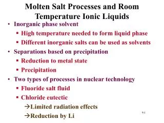
Molten Salt Processes and Room Temperature Ionic Liquids. Inorganic phase solvent High temperature needed to form liquid phase Different inorganic salts can be used as solvents Separations based on precipitation Reduction to metal state Precipitation

E N D
Molten Salt Processes and Room Temperature Ionic Liquids • Inorganic phase solvent • High temperature needed to form liquid phase • Different inorganic salts can be used as solvents • Separations based on precipitation • Reduction to metal state • Precipitation • Two types of processes in nuclear technology • Fluoride salt fluid • Chloride eutectic • Limited radiation effects • Reduction by Li
Molten Salt Reactor • Fluoride salt • BeF2, 7LiF, ThF4, UF4 used as working fluid • thorium blanket • fuel • reactor coolant • reprocessing solvent • 233Pa extracted from salt by liquid Bi through Li based reduction • Removal of fission products by high 7Li concentration • U removal by addition of HF or F2
Pyroprocesses • Electrorefining • Reduction of metal ions to metallic state • Differences in free energy between metal ions and salt • Avoids problems associated with aqueous chemistry • Hydrolysis and chemical instability • Thermodynamic data at hand or easy to obtain • Sequential oxidation/reduction • Cations transported through salt and deposited on cathode • Deposition of ions depends upon redox potential
Electrochemical Separations • Selection of redox potential allows separations • Can use variety of electrodes for separation • Developed for IFR and proposed for ATW • Dissolution of fuel and deposition of U onto cathode • High temperature, thermodynamic dominate • Cs and Sr remain in salt, separated later • Free energies • noble metals • iron to zirconium • actinides and rare earths • Group 1 and 2 • Solubility of chlorides in cadmium
Electrorefining Electrorefining
Spent Fuel Decladding: Feed Material Step 1 • Support hardware remove from assembly • Pins chopped • Existing methods • Oxide fuel separated from cladding • Oxide fuel sent to reduction process • Cladding use as Zr source for ATW fuel • Offgas released in decladding collected and sent to storage/disposal
Reduction of oxide fuel Step 2 Input • 445 kg oxide (from step 1) • 135 kg Ca • 1870 kg CaCl2 Output • 398 kg heavy metal (to step 3) • To step 8 • 2 kg Cs, Sr, Ba • 189 kg CaO • 1870 kg CaCl2 • 1 kg Xe, Kr to offgas Metal Operating Conditions T= 1125 K, 8 hours 4 100 kg/1 PWR assembly
Anode Uranium Separation Step 3 Input 398 kg heavy metal (from step 2) • 385 kg U, 20 kg U3+(enriched, 6%) • 3.98 kg TRU, 3.98 kg RE • 188 kg NaCl-KCl Output • 392 kg U on cathode • To step 4 (anode) 15 g TRU, 14 g RE, 2.8 kg U, 5 kg Noble Metal • Molten Salt to step 5 • 10 kg U, 3.9 kg TRU, 3.9 kg RE, 188 kg NaCl-KCl Operating Conditions T= 1000 K, I= 500 A, 265 hours 4 100 kg/1 PWR assembly
Anode Polishing Reduces TRU Discharge Step 4 Input from Anode #3 • 5 kg Noble Metal, 2.8 kg U, 15 g TRU, 14 g RE, 1.1 kg U3+, 18.8 kg NaCl-KCl Output Anode • 5 kg Noble Metal, 0.15 g U, 0.045 g TRU, 0.129 g RE Cathode • 1.5 g Noble Metal, 2.9 kg U Molten Salt (to #3) • 28 g Noble Metal, 1 kg U, 15 g TRU, 14 g RE, 18.8 kg NaCl-KCl Metal Operating Conditions T= 1000 K, I= 500 A, 2 hours 1 PWR assembly
Electrowinning Provide Feed for Fuel Step 5 Input from molten salt from #3 • 10 kg U, 4 kg TRU, 4 kg RE, 4.3 kg Na as alloy, 188 kg NaCl-KCl Output Cathode • U extraction 9.2 kg • U/TRU/RE extraction, 1 kg U, 4 kg TRU, 0.5 kg RE Molten Salt (to #7) • 3.5 kg RE, 192 kg NaCl-KCl Metal Operating Conditions T= 1000 K, I= 500 A, 3.7 hours for U/TRU/RE, 6.2 hours for U 1 PWR assembly
metal ATW Fuel Fabrication Step 6 Vacuum Casting Furnace Input • From #5 • 1 kg U, 4 kg TRU, 0.5 kg RE • From #1 • 14.7 kg Zr Output 20 kg alloy fuel Fuel Preparation • Rods machined to proper diameter • Rods cut into pellets for use in fuel pins Metal Operating Conditions: Vacuum Casting T= 1900 K, moderate vacuum
Reduction of Rare Earths Step 7 Input • Molten Salt from #5 • 3.4 kg RE • 1.7 kg Na as alloy • 188 kg NaCl-KCl Output • Molten Salt (to step 3) • 189 kg NaCl-KCl • Metal Phase • 3.4 kg RE Metal Operating Conditions T= 1000 K, 8 hours
Recycle Salt: Reduction of Oxide Step 8 Input • Chlorination • 189 kg CaO, 1870 kg CaCl2, 239 kg Cl2 • Electrowinning • 2244 kg CaCl2 Output • Chlorination • 2244 kg CaCl2, 54 kg O2 • Electrowinning (to #2) • 1870 kg CaCl2, 135 kg Ca, (239 kg Cl2) Operating Conditions T= 1000 K, I= 2250 A, 80 hours
ATW Assembly for Feed Material Step 9 • ATW assembly is used to produce feed material for electrorefining process • Hardware removed from assembly • ATW fuel chopped into small sections • Cladding is sent to storage • Offgas is collected and stored
Anode TRU U, TRU, and Fission Product Separation Step 10 Input • 45 kg from Step 9 (includes Zr) • Includes 9.5 kg TRU, 0.5 kg RE Output • Anode • 33 kg NM, 2 kg U • Molten Salt (to #11) • Small amounts of U, TRU, RE • Cathode (to #12) • Most TRU, RE Operating Conditions T= 1000 K, I= 500 A, 6.7 hours
Electrowinning TRU for Salt Recycle Step 11 Input from molten salt from #10 • 1.7 kg U, 7.4 kg TRU, 0.5 kg RE, 2.8 kg Na as alloy, 188 kg NaCl-KCl Output Cathode (to #12) • U/TRU/RE extraction, 1.7 kg U, 7.4 kg TRU, 0.1 kg RE Molten Salt (to #13) • 0.4 kg RE, 191 kg NaCl-KCl Metal Operating Conditions T= 1000 K, I= 500 A, 6.1hours for U/TRU/RE Salt from 10 electrorefining systems
metal ATW Fuel Fabrication Step 12 Vacuum Casting Furnace Input • From #10 and #11 • 1.7 kg U, 17 kg TRU, 0.5 kg RE, • From #1 • 52 kg Zr Output 71 kg alloy fuel Fuel Preparation • Rods machined to proper diameter • Rods cut into pellets for use in fuel pins Metal Operating Conditions: Vacuum Casting T= 1900 K, moderate vacuum Four Batches required to prepare fuel alloy
Reduction to Remove Rare Earths Step 13 Input • 0.4 kg RE (from #11), 188 kg NaCl-KCl, 0.2 kg Na as alloy Output • Molten Salt • 188 kg NaCl-KCl • Metal Phase • 0.4 kg RE Metal Operating Conditions T= 1000 K, 8 hours
Treatment Scheme • To treat 70000 metric tons of spent fuel • 2 MT/day in each plant • 2 chemical plants required to treat LWR and ATW waste • 300 day/year at 24 hours/day Need 60 years • For ATW waste • 360 kg/day/plant
Project TRU Waste to Repository • Results based on simulations • LWR, 12 ppm TRU • ATW spent fuel, 10 ppm TRU • Should expect high amounts due to engineering scale • Total TRU to repository • In 60 years, < 300 kg TRU in approximately 900 MT
Segregated Waste Streams • Uranium • Low activity of waste • Metals • Spent fuel clad and assembly to repository • Transition metals and lanthanides • Oxides to repository • Active Metals into engineered containers • No separation of fissile metals
Reprocessing Overview The oxide fuel is dispersed in a molten (800 C) CaCl2 /CaF2 salt along with calcium metal and reduced to a metal. The reduced metals are dissolved in a molten Cu - 40% Mg - Ca receiver alloy. Uranium exceeds the solubility limits in this receiver alloy and precipitates out as a solid metal. Pu, other actinides, rare-earths, and noble metal fission products accumulate in the receiver alloy. The the alkali metals (Rb and Cs), alkali-earths (Sr and Ba),and remaining iodine and bromine accumulate in the CaCl2/CaF2 salt. The salt contains CaO from the reduction process. The CaO is electrolytically reduced to metal for reuse.
Overview • The actinides are separated from the acceptor alloys by distilling the Cd-Mg alloy. • The electrorefining process described above is then used to purify the final metal uranium and actinide product. • Because there is no water to enhance criticality, containers typically can have 20 or 30 kg of fissile material
Overview • Introduction to Room Temperature Ionic Liquids • Physical Properties • Coordination Chemistry • Metal Deposition • From Lecture of Dave Costa, LANL
Room Temperature Molten Salts as Alternatives to Traditional Actinide Recovery Processes • Project Goal: Develop a room temperature ionic liquid flow sheet for the electrochemical recovery and purification of uranium and plutonium from spent nuclear feed stocks. • Proliferation resistant recovery of uranium/plutonium • Uranium/Plutonium metal production • Zero effluent discharge operations • Room temperature operation • Greater criticality safely margin
Criticality calculations for Pu metal - solution systems Metal-Water Mix Metal-AlCl3 Mix Metal-BF4 Mix 1.0E+04 1.0E+03 1.0E+02 Critical Mass (kg) 1.0E+01 1.0E+00 1.0E-01 1.0E+00 1.0E+01 1.0E+02 1.0E+03 1.0E+04 1.0E+05 Pu Concentration (g/liter) Harmon, C.D.; Smith, W.H.; Costa, D.A. Rad. Phy Chem.60, 157, (2001). Criticality calculations for plutonium metal-room temperature ionic liquid solutions
Ionic Liquid Cations Bonhote Inorg. Chem. 1996, 35, 1168 N N N N N N N N N N mp = 150 °C ambient temperature liquids... mp = 56 °C O MacFarlane J. Phys. Chem.1999, 103, 4164 N N O N N N O
Ionic Liquids: Quaternary Ammonium Cations MacFarlane J. Phys. Chem. B.1998, 102, 8860
O O N S S C F F C 3 3 O O Physical Properties Density (g/mL) 1.52 1.45 1.39 1.38 1.35 1.32 1.30 Reference: H2O = 1.002 cP C6H6 = 0.64 cP Olive Oil = 81 Reference: 0.1M KCl = 14mS/cm
Electrochemical Windows of Ionic Liquids The electrochemical window of an imidazolium NTf2 salt is compared with a typical ammonium ionic liquid. The CV trace is referenced to Ag/AgOTf and confirmed with ferrocene.
Potential Ionic Liquid Anions 0.1 M NaCl/H2O H3PO4 0.1 M Bu4N+ -B(C6F5)4/CH2Cl2 cyclohexanol ethylene glycol • Bonhote et. al. Inorg. Chem. 1996, 35, 1168. • Dupont et. al. Organometallics 1998, 17, 815. -N(SO2CF3)2 abbreviated as -NTf2
Structural Characterization of a Room Temperature Ionic Liquid P21/n a = 12.225(3) Å b = 8.547(2) c = 34.322(8) b = 92.749(4)° R = 6.8% Top view 3dx2-y2 S(1)—N(3) = 1.571(4) Å S(2)—N(3) = 1.580(4) S—Oaverage = 1.425 S(1)–N(3)–S(2) = 126° Side view N—S in H3N—SO3– = 1.75 Å N—S in HN(SO2CF3)2 = 1.644 Å 3dz2
Coordination Modes of N(SO2CF3)2 See Chem. Commun., 2005, 1438-1440
Coordination Chemistry of NTf2: Synthesis of Fp–NTf2 n(CO): 2005, 1945 cm-1 2071, 2029 cm-1 2020, 1960 cm-1
Coordination Chemistry of NTf2: Synthesis of Fp–NTf2 n(CO): 2005, 1945 cm-1 2071, 2029 cm-1 2020, 1960 cm-1 n(CO) BF4 2072, 1994 cm-1 SbF6 2074, 2039 ClO4 2071, 2009 OSO2CF3 2068, 2017
Coordination Chemistry of NTf2: Synthesis of Fp–NTf2 n(CO): 2005, 1945 cm-1 2071, 2029 cm-1 2020, 1960 cm-1 Fe(1)–N(1) 2.084(4) Å N(1)–S(1) 1.630(4) N(1)–S(2) 1.643(4) S–Oave 1.421 S(1)–N(1)-S(2) 117.1(2)° n(CO) BF4 2072, 1994 cm-1 SbF6 2074, 2039 ClO4 2071, 2009 OSO2CF3 2068, 2017
Synthesis of Cp2Ti(NTf2)2: Novel Metal–Oxygen Binding Mode Ti(1)—O(1) = 2.050(3) Å N(1)—S(1) = 1.523(5) S(1)—O(1) = 1.467(4) N(1)—S(2) = 1.613(5) S(1)—O(2) = 1.416(4) S(1)–N(1)–S(2) = 126.1°
Influence of –NTf2 Coordination on E1/2 Values Reference: Ag/AgOTf/EMINTf2 Working electrode: platinum Scan rate: 50 mV/s Cp2Ti(NTf2)2 E1/2 = -0.103 V Cp2TiCl2 E1/2 = -1.031 V ∆E1/2 = 0.928 V
Cyclic Voltammetry of [UCl6]2- Salts U(V), U(IV), and U(III) are all stable species for [UCl6]-n (n=1, 2, 3) 5+/4+ 4+/3+ Reference: Ag/AgOTf/EMINTf2 Working electrode: platinum Scan rate: 50 mV/s Reversible 5+/4+ E1/2 = 0.27 V Reversible 4+/3+ E1/2 = -1.98 V
Bulk Electrolysis of [UCl6][EMI]2 in [EMI][NTf2] Stirred Solution Voltammograms: 1.5 mm GC disc, 3 mV/s Pale Blue Pale Blue Yellow U(IV) U(V) U(IV) • Eapp during bulk was set 300 mV positive of E1/2 for U(IV)/U(V) couple • [U(V)Cl6]- is stable in [EMI][NTf2] on the bulk electrolysis time scale • Coulometry was 94% efficient for a 1-electron oxidation process