Introduction Solid-Propellant Rocket Motors Liquid-Propellant Rocket Engines
500 likes | 1.23k Vues
AE 8129 Rocket Propulsion. Introduction Solid-Propellant Rocket Motors Liquid-Propellant Rocket Engines Hybrid Rocket Engines Air-Breathing Rocket Engines Non-Chemical Space Propulsion Systems. Pressure-Fed Hybrid Rocket Engine. Diagram courtesy of Stanford University.

Introduction Solid-Propellant Rocket Motors Liquid-Propellant Rocket Engines
E N D
Presentation Transcript
AE 8129 Rocket Propulsion Introduction Solid-Propellant Rocket Motors Liquid-Propellant Rocket Engines Hybrid Rocket Engines Air-Breathing Rocket Engines Non-Chemical Space Propulsion Systems
Pressure-Fed Hybrid Rocket Engine Diagram courtesy of Stanford University
Introduction to Hybrid Rocket Engines (HREs) • A compromise between the simplicity of SRMs and the performance of LREs; some safety, material availability and environmental advantages • Engine is started, and burn and corresponding thrust can be modulated (throttled) through to completion, like an LRE • Competitive for single- or multi-stop/start applications requiring medium performance (i.e., potentially higher Ispthan SRM) • Thrust range: newtons (thruster) to mega-newtons (launch vehicle first-stage engine)
*frozen LOX valve inhibited oxidizer delivery to engine, then subsequent hydrogen peroxide fire broke out AMROC’s SET-1 launch vehicle on launch pad, 1989 (*aborted launch; SET = Single Engine Test; LOX/HTPB)
SpaceShipOne First production HRE usage Images courtesy of Scaled Composites LLC
HRE test firing (lots of aft flame in exhaust plume suggests significant afterburning in reacting with outside air)
HRE test firing, showing Mach diamonds (comprised of oblique shock and rarefaction waves) in exhaust plume
Nominal exhaust flow patterns for an overexpanded supersonic nozzle (upper diagram) and an underexpanded supersonic nozzle (lower diagram), revealing diamond-shaped wave patterns
HRE Design Considerations • Wide choice of solid fuels to choose from, where factors such as energy, regression rate, structural robustness and availability come into play, e.g., modest-energy plastics like polyethylene are stiff, medium-energy rubbers like HTPB are a bit soft, high-energy waxes like paraffin are really soft • Lower fuel regression rates may force the use of multiple ports, to get the burning surface area up in value
Single (central) port and multiple port fuel grain designs, depending on required burning surface area needed
HRE Oxidizer Feed System • Three main categories: 1) self-pressurized feed 2) pressure-feed, and 3) turbopump-feed • Self-pressurization of some oxidizers like nitrous oxide (control transition temperature from liquid to gas) or hydrogen peroxide (catalyst used to instigate transition from liquid to gas) • Pressure-feed approach is the present common choice for higher performance, using a high-pressure gas like He or N2 to drive the oxidizer from storage to the injector plate at around 20% greater pressure than operating combustion chamber pressure pc
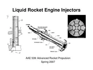
Injectors • Injectors atomize the incoming liquid oxidizer spray (break into small droplets) and encourage spreading of oxidizer droplets/vapor over the solid fuel internal port surface • Ignition of solid fuel initiated by various means (metal wool, igniter paste, secondary oxidizer and/or liquid/gas fuel injection, electrically-heated nichrome wire, spark plug, pyrotechnic cartridge, etc.)
Pre- and Post-Combustion Chambers • Commonly see the use of a pre-combustion chamber between the head-end injector plate and the fuel grain, to allow for better oxidizer atomization and spread pattern • Occasionally see the use of a post-combustion chamber between the end of the fuel grain and the nozzle entry, to allow for further reaction time, and to permit additional oxidizer injection aft
Orbitec vortex design with head end and aft oxidizer injection
Combustion Processes • Equilibrium chemical reaction between nitrous oxide and paraffin wax may be approximated by the following: 85N2O(g) + C28H58(s) 85N2(g) + 29H2O(g) + 28CO2(g) + heat
Fuel Surface Regression • Standard empirical model, based on axial mass flux G = u: , 0.4 < n < 0.85 • For preliminary design, and for regression rate data reduction, common to assume: Go =
Fuel Regression (cont’d) • Greatrix/Gottlieb convective heat feedback model analogous to HRE mass-flux dependent burning: , general case , typical case, ro small (note dependence on G)
Theoretical and experimental data for burning rate as a function of mass flux, HTPB/GOX propellant A, and paraffin/ GOX propellants C & D
Internal Ballistic Analysis • Preliminary estimate of chamber pressure, using empirical regression law: • For thrust, etc. :
Internal Ballistics (cont’d) Stoichiometric mixture ratio: Stoichiometric length (cylindrical grain, fixed oxidizer rate): , alternate expression
Typical design issues with conventional hybrid rocket engine: LST < f , early in firing, some unreacted fuel ablated from aft fuel surface, fuel decomposition gas enters nozzle and afterburns with outside air in exhaust plume LST > f , later in firing, some unreacted oxidizer enters nozzle, may do oxidization damage to nozzle surface
Non-Combustive Ablation , ablation rate of fuel, aft of stoichiometric length
Predicted pressure- and thrust-time profile for small cylindrical-grain fixed-oxidizer-rate HRE; first dip is grain burnback beginning to meet outer wall limit; second dip is transition point where LST begins to exceed the fuel grain length
Combustion Instability in HREs • Susceptible to both axial and transverse symptoms in the combustor (pressure waves); higher frequencies more damaging than lower frequencies, at high wave amplitudes • At low wave frequencies, one can observe symptoms of significant amplitude associated with feed system instability (related to injectors and upstream plumbing) • Cold outside air temperatures tend to cause instability issues