Download
1 / 119
1.59k likes | 2.57k Vues
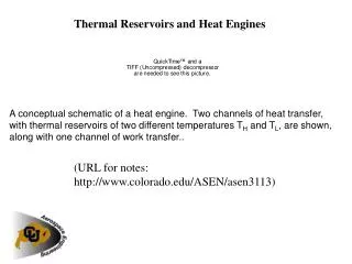
THERMAL ANALYSIS OF LIQUID ROCKET ENGINES. Mohammad H. Naraghi Department of Mechanical Engineering Manhattan College Riverdale NY 10471. Introduction to Cooling Methods. Combustion gases are 4000 to more than 6000 o F

E N D
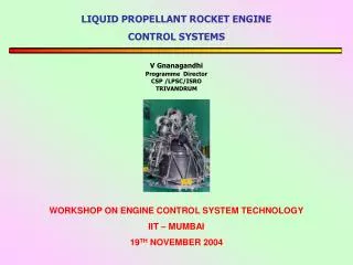
THERMAL ANALYSIS OF LIQUID ROCKET ENGINES Mohammad H. Naraghi Department of Mechanical Engineering Manhattan College Riverdale NY 10471
Introduction to Cooling Methods • Combustion gases are 4000 to more than 6000oF • Heat transfer rates from hot-gases to the chamber wall are 0.5 to over 130 BTU/in2s • A cooling system is needed in order to maintain engine integrity
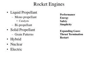
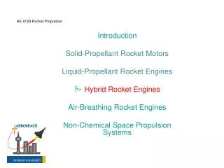
Chamber and Nozzle Cooling Techniques • Regenerative cooling • Dump cooling • Film cooling • Transpiration cooling • Ablative cooling • Radiation cooling
Types of Cooling Channel Rectangular cooling channels
A rocket chamber nozzle made of a copper alloy with machined cooling channels (no closeout)
Tubular Cooling Channel Chamber jacket The number of coolant tubes required is a function of the chamber geometry, the coolant weight flow rate per unit tube, the maximum allowable tube wall stress, and fabrication consideration
Tubular Cooling Channel Chamber jacket Tubular cooling channel configuration at throat area(parts of nozzle with small diameter)
Copper NARloy-Z SS-347 Glidcop Inconel718 Amzirc Columbium SS-347 Nickel Copper Monel Wall Materials Coating: Close-out: Wall: • Platinum • Nicraly • Soot • Zirconia
Propellants • H2-O2 • RP1 (JET-A) C12H23-O2 • Methane-LOX CH4-O2 • Hydrogen Peroxide
Coolants • Liquid Hydrogen • Liquid Oxygen • Water • RP1 (JET-A) • Methane • Hydrogen Peroxide
Issues in Designing Cooling Passages • Keeping nozzle and wall temperatures below material limits • Keep pressure drop reasonable • Overcooling is detrimental to engine performance • Coolant exit condition be suitable for injector or running a turbo pump
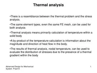
Modes of Heat Transfer Coolant convection Conduction within the wall Convection and radiation from combustion gases (hot-gases). All these modes of heat transfer must be conjugated
Hot-gas 2 1 n 3 Modeling Heat Transfer in Regeneratively Cooled EngineTypical Nozzle Broken into a Number of Stations Coolant in
Typical Cross-Section of Nozzle Due to symmetry calculation can be performed for a half cooling channel.
Convection from Hot-Gases • The first step is to determine hot-gas thermodynamics and transport properties • CEA (Chemical Equilibrium with Applications) code can be used to evaluate the hot-gas properties. This program is a public domain code and can be downloaded from NASA Glenn’s site:http://www.grc.nasa.gov/WWW/CEAWeb/ • Typical results of CEA with rocket option for the SSME
Hot-Gas Side Convective Heat Flux Or n is the station number TGAW and iGAW are adiabatic wall temperature and enthalpy TGW and iGW are gas-side wall temperature and enthalpy hG is the gas-side heat transfer coefficient is constant pressure hot-gas specific heat at reference condition
Adiabatic Wall Temperature (Enthalpy) The reference enthalpy of the gas side, is given by (Eckert): The adiabatic wall enthalpy (Bartz and Eckert) Subscripts S and 0 represent static and stagnation conditions
Hot-Gas Side Convective Heat Transfer Coefficient Dittus-Bolter correlation
Hot-Gas Side Convective Heat Transfer Coefficient Bartz correlation Is correction factor for property variation across the boundary layer
Computational Methods for Hot-Gas Heat Flux Calculations • Boundary Layer analysis using available codes, such as TDK (Two Dimensional Kinetics) • TDK has two boundary layer modules (BLM, Boundary Layer Module, and MABL, Mass Addition Boundary Layer) • MABL can be used for transpiration cooling • Computation time for TDK is approximately two minutes • CFD codes
CFD Results, Static Temperature for the Regen Part of the SSME
Comparison Between Heat Fluxes Based on Various Methods for the SSME
Wall Conduction Models • Two approaches can be used for wall • conduction: • Simple one-dimensional heat conduction • Two or Three-dimensional finite-difference or finite-element methods
One-dimensional wall conduction TCAW 1/hFhCAC t/kA 1/hGA TGAW
TCAW 1/hFhCAC t/kA 1/hGA TGAW One-dimensional wall conduction Fin efficiency l 2
Soot Layer Thermal Resistance For engines with hydrocarbon fuel with Pc< 1500 psi From Modern Engineering for Design of Liquid-Propellant Rocket Engines, D. K. Huzel and D. H. Huang Progress in Astronautics and Aeronautics, Vol. 147, 1992
Soot Layer thickness For the converging section: tsoot = 0.0041213(A/At) + 0.0041023 1<A/At<2 tsoot = 0.01234 2<A/At For the diverging section: tsoot = -0.0000442(A/At)2 + 0.0011448(A/At) + 0.0070920 1<A/At<12 tsoot=0.01445 12<A/At tsootare in inches
i,j+1,n i,j,n-1 i-1,j,n i,j,n i+1,j,n i,j,n+1 i,j-1,n 3-D Finite Difference Method Energy balance for a typical middle node
3-D Finite Difference Method i,j+1,n i,j,n-1 Energy balance for a typical surface node i-1,j,n i,j,n i+1,j,n Qr i,j,n+1 Qc
Sample Results of Wall Temperature Distribution for the SSME
Sample Results of Wall Temperature Distribution for the SSME Throat
Sample Results of Wall Temperature Distribution for an Engine with Pass-and-half Tubular Cooling Channels
Sample Results of Wall Temperature Distribution for an Engine with Pass-and-half Tubular Cooling Channels
Coolant Flow Convection Two approaches can be used for coolant flow analysis: • One dimensional flow and heat transfer • Multidimensional CFD analysis
Coolant Flow Convection • One-dimensional channel flow with variable cross-section for calculation pressure drop. • Heat transfer to coolant is evaluated based on the heat transfer coefficients calculated using Nu=f(Re,Pr) correlations. • GASP (Gas Properties) and WASP (Water and Steam Properties) are used for evaluating coolant properties (these programs are public domain codes).
Variables Effecting Coolant Convection • Surface roughness • Entrance effect • Curvature effect • Using swilers • Cooling channel contraction and expansion • Pressure drop • Cooling channel tolerance and blocked channel
Cooling Channel Heat Transfer Coefficient for Liquid Hydrogen Where
Cooling Channel Heat Transfer Coefficient for RP-1 Shell correlation Rocketdyne correlation
Heat Transfer Coefficient for Oxygen psia Where
Coking Characteristics of RP1 Range of Conditions Tested During RP1 Cooling Claflin, S.E., and Volkmann, J.C., “Material; Compatibility and Fuel Cooling Limit Investigation for Advanced LOX/Hydrocarbon Thrust Chambers,” AIAA 90-2185, AIAA/SAE/ASME/ASEE 26th Joint Propulsion Conference, Orlando, FL, 1990.