Download

1 / 12
130 likes | 193 Vues
Learn the fundamentals of steady-state heat transfer analysis, including element types, material properties, and assemblies in ANSYS. Understand thermal loads, contact settings, and more.

E N D
Appendix Six Thermal Analysis
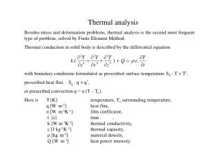
Basics of Steady-State Heat Transfer • A steady-state thermal analysis is performed to determine the thermal response under applied steady-state loads • Temperatures and heat flow rate are usually the items of interest, although heat fluxes can be reported as well. • The general thermal equation is as follows:where t is time and {T} is temperature, [C] is the specific heat (thermal capacitance) matrix, [K] is the conductivity matrix, and {Q} is the heat flow rate load vector. • In a steady-state analysis, all time-dependent terms are removed. However, nonlinearities can be present: March 29, 2005 Inventory #002215 A6-2
… Elements Used • In Simulation, the following elements are used: • Solid bodies are meshed with 10-node tetrahedral or 20-node hexahedral elements • SOLID87 and SOLID90 • Surface bodies are meshed with 4-node quad shell elements • SHELL57 using real constants • (SHELL131 or SHELL132 are currently not used.) • Line bodies are meshed with 2-node line elements • LINK33 using real constants • An equivalent cross-sectional area, as defined in DesignModeler, is used for LINK33 • For thermal-stress analyses, a coupled-field element is not used. The thermal-stress analysis is performed sequentially, so the above thermal elements are used, then the temperature field is read into corresponding structural elements. March 29, 2005 Inventory #002215 A6-3
… Material Properties • Thermal conductivity is input into ANSYS as MP commands. • For temperature-dependent thermal conductivity, the appropriate MPTEMP and MPDATA commands are issued • Although specific heat may be defined in the “Engineering Data” branch, it is currently unused and not passed to ANSYS • MP,C commands are not written for specific heat March 29, 2005 Inventory #002215 A6-4
… Assemblies – Solid Body Contact • Internally, thermal contact for solid faces is defined with CONTA174 and TARGE170 elements. • KEYOPT(1)=2 set for thermal DOF only • KEYOPT(12) is based on contact type used • For example, bonded type is KEYOPT(12)=5. KEYOPT(2), KEYOPT(5), KEYOPT(9), and FKN are also set. These contact settings are most critical for structural contact, so the various default settings are outlined in Chapter 4. • Default thermal contact conductance (TCC) is based on highest value of thermal conductivity of materials and overall geometry size • TCC=KXX*10,000/ASMDIAG • KXX is of highest thermal conductivity value of used materials • ASMDIAG is diagonal of overall ‘bounding box’ of assembly • TCC is not used for MPC (KEYOPT(2)=2 on CONTA174) • If Normal Lagrange formulation is set, KEYOPT(2) reset to 0. March 29, 2005 Inventory #002215 A6-5
CONTA175 elements TARGE170 elements … Assemblies – Surface Body Contact • Internally, any contact including an edge (solid body edge or surface edge) results in asymmetric contact with CONTA175 for the edge and TARGE170 for the edge/face • Undocumented KEYOPT(1)=2 is set for thermal contact • Contact involving solid edges default to pure penalty method • Contact involving surface edges use MPC formulation. Instead of “target normal,” if search direction is “pinball region,” KEYOPT(5)=4 set on companion TARGE170 element. • For bonded contact (default), both use KEYOPT(12)=5 and KEYOPT(9)=1. • For surface faces in contact with other faces, standard surface-to-surface contact is used, namely CONTA174 and TARGE170 March 29, 2005 Inventory #002215 A6-6
… Assemblies – Spot Weld • Internally, spot welds are defined as a set of LINK33 elements. The spot weld is defined with one link element, and the top and bottom of the spot weld is connected to the shell or solid elements with a ‘spider web’ of multiple links. • The LINK33 elements usesame thermal conductivityas underlying materials butwith a circular cross-sectionwith radius=5*thickness ofunderlying shells • Figure on right shows twospot welds between two sets of shell elements, which aremade translucent for clarity. March 29, 2005 Inventory #002215 A6-7
… Thermal Loads in ANSYS • The internal representation of loads in ANSYS: • Heat flow for an edge or vertex is a heat flow rate (F,,HEAT) • Heat flux or heat flow for a surface is surface load (SF,,HFLUX) • Internal heat generation is applied as a body load (BFE,,HGEN) • Given temperature is applied as a constraint (D,,TEMP) • Perfectly insulated condition internally removes any loads applied in Simulation on those surface(s). • Convection is defined by surface effect SURF152 elements • Bulk temperature and film coefficient is applied on the surface effect elements (SF,,CONV,film,bulk) • If temperature-dependent film coefficients exist, these are defined with a temperature-dependent HF material property (MPDATA,HF). The film coefficient value applied will be “–HF_number,” and ANSYS knows to use the referenced HF material property number. • KEYOPT(8) is set to be consistent with temperature evaluation of h(T), such as evaluate h(T) based on surface temperature. March 29, 2005 Inventory #002215 A6-8
… Solution Options in ANSYS • The solver selection for direct vs. iterative: • The solvers used are either the direct sparse solver (EQSLV,SPARSE) or the PCG solver (EQSLV,PCG) • The JCG solver is not used in thermal analyses • A simplified discussion between the two solvers: • If given the linear static case of [K]{x} = {F}, Direct solvers factorize [K] to solve for [K]-1. Then, {x} = [K]-1{F}. • This factorization is computationally expensive but is done once. • Iterative solvers use a preconditioner [Q] to solve the equation [Q][K]{x} = [Q]{F}. Assume that [Q] = [K]-1. In this trivial case, [I]{x} = [K]-1{F}. However, the preconditioner is not usually [K]-1. The closer [Q] is to [K]-1, the better the preconditioning is, and this process is repeated - hence the name, iterative solver. • For iterative solvers, matrix multiplication (not factorization) is performed. This is much faster than matrix inversion if done entirely in RAM, so, as long as the number of iterations is not very high (which happens for well-conditioned matrices), iterative solvers can be more efficient than sparse solvers. • The main difference between the iterative solvers in ANSYS — PCG, JCG, ICCG — is the type of pre-conditioner used. March 29, 2005 Inventory #002215 A6-9
… Solution Options in ANSYS • Solver working directory: • The ANSYS input file is written as “ds.dat” in the solver directory. The output file is “solve.out” and can be viewed in the “Worksheet” tab of the “Solution Information” branch. • ANSYS is executed in batch mode (-b) as a separate process. During solution, the results file .rth is written. The results are also read in and XML results files are generated in batch mode. The XML files are then read into Simulation. • All associated ANSYS files have default jobname of “file” and are deleted after solution, unless changed in “Tools > Options… > Simulation: Solution > Save Ansys Files”. March 29, 2005 Inventory #002215 A6-10
… Solution Options in ANSYS • Some solution options are also defined: • Solution control is used • This is different from structural analyses in Simulation where Solution Control is turned off • ANSYS shape checking is turned off (SHPP,OFF) • If nonlinear, the number of substeps (NSUBST,1,10,1) and number of equilibrium iterations (NEQIT,20) are defined • CNVTOL also set, where minimum reference heat flow rate is defined as 1e-6 W • Only Simulation-supported results is output with OUTRES, not everything by default • Results are later written to XML files in /POST1, which are then read back into Simulation. Hence, Simulation does not directly read the results from the .rth file March 29, 2005 Inventory #002215 A6-11