Analysis of Rocket Flights
470 likes | 629 Vues
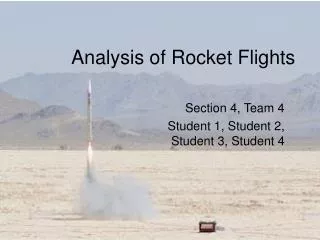
Analysis of Rocket Flights. Section 4, Team 4 Student 1, Student 2, Student 3, Student 4. Temperature Predictions. Decrease in temperature upon ascent Rise in temperature upon descent Further increase after landing. Thermistor 3 (middle of rocket body, on surface). Thermistor 2 (on fin).

Analysis of Rocket Flights
E N D
Presentation Transcript
Analysis of Rocket Flights Section 4, Team 4 Student 1, Student 2, Student 3, Student 4
Temperature Predictions • Decrease in temperature upon ascent • Rise in temperature upon descent • Further increase after landing
Altimeters • Expect decrease in pressure with increase in altitude, and vice versa • Used barometric equation to find altitude • Calibrated sensors in lab using vacuum chamber
Flight Modeling (2-D) T T z z y θ y CG CG r r CP Wind CP Wind mg mg D D
Euler’s Integration • Method for numerical integration • Iterative • For given a(t) and initial conditions for x and v: v(t+Δt)=v(t)+a(t)*t x(t+Δt)=x(t)+v(t)*t
az Az y ay az ax ax Ax Ay ay IMU Analysis: Mudd IIIC (Large) Rocket • Rotation from local to global axes • Euler integration of rotation matrix
Processing Algorithm (Matlab) Calibrations Acceleration Filtering (optional) Raw RDAS Data (counts) Local Acceleration (m/s2) Global Acceleration (m/s2) Filtered Global Acceleration (m/s2) Euler integration Calibrations Rotation Matrix (radians/sec) Global Velocity (m/s) and Position (m) Local Rotation Rate (radians/sec) Euler integration Local Rotation Angle (degrees)
z wind E80 teams Acceleration Filtering (Descent Plot)
Bad Data • Mudd IIIA IMU rocket • Failure to eject parachute • Flat spin crash after apogee • WHY? http://www.tribuneindia.com/2002/20020715/world.htm
Acceleration Data… • Very pronounced 0.2149 Hz oscillations • Possible causes: camera interference, camera overpowering • Band-stop filter might be able to retrieve data
Theoretical Analysis • Tap tests on hollow tube are inaccurate • Mass spring damper system
Spring-Mass-Damper Model • Rocket can be modeled as a single degree of freedom spring-mass-damper system. • Effective mass, m • Spring constant, k • Damping • Half-Power Bandwidth Predicted Resonance Frequency
Analysis • No control variables! • Treat Sensor 10 as input. • Create FRFs of other sensors to see relative peaks Sensor 10
FRF plots • Removed DC offset • fdomain.m used to generate Fourier Coefficients • Relative Amplitudes • First set of data is not trustworthy • Second set of data has more coherent peaks • Used 1st second of data, short motor burn time
1st Set of Data Results • Peak around 60 or 70 Hz • Other peaks are inconsistent • Sensor 15 seems to be malfunctioning • Locally, 3 sensors show local peaks between 60-80 • No video
2nd Set of Data Results • Consistent peaks at 64 Hz • Possible peaks around 30 Hz, but not consistent • Sensors 1, 3, and 8 are 13 show peak frequencies • Sensor 13 farther away from the input source
Noises • Only 64 Hz showed in every FRF • Others are jumbled by the noise • Running averages smoothes out the data too much. • Too little data during the 1st second of input • Ineffective way of removing noise
Mode Shapes • Absolute magnitude of Fourier Coefficients vs Relative Sensor Distances • Sensor 10 was normalized as “0” point.
Results from FRF • Not enough frequencies to test all 3 mode shapes • Does not deal well with noise, especially with highly aliased data
Problems with FFT • Using just FFT coefficients to calculate Frequency Response Functions assumes a clean periodic signal. • The rocket data is neither. • A better estimator is Power Spectral Density (PSD).
Power Spectral Density Auto power spectral density Cross power spectral density Frequency Response Function
H(jw) PSD and Noise x(t) v(t) y(t) n(t) Assume n(t) is unrelated to v(t) 0
Hamming Window Time Domain Frequency Domain
Averaging Overlap Overlapping windowed segments by 50% minimizes attenuation of time domain signal near the end of segment
Waterfall Analysis FRF of Sensor 5 over time magnitude (dB) time (.1 sec) freq (Hz)
Conclusions • Thermistor behavior depends on location • Euler Integration Method not sufficient to model whole flight path • Spring-Mass-Damper model can simplify system to find theoretical resonance • FFT method of finding FRF is not consistent due to large noise component • PSD method gives much sharper peaks in FRF
Interesting Precautions... • Check battery…sensors are sensitive! • Wait until last moment to turn on R-DAS and video camera…otherwise, ejection charge could go off early! • Don’t try to catch rocket…it may have a chute, but it’s still falling fast!
Acknowledgements • The professors and proctors who helped to make this beta-test a success. • All of our classmates for their infinite support and advice during this semester • Student A for a discussion on the causes of small rocket IMU corruption • Student B for his help with setting up the Single Degree of Freedom model
References • E80 The Next Generation Spring 2008, http://www.eng.hmc.edu/New E80/index.html. • R. Wang, http://fourier.eng.hmc.edu/e80/inertialnavigation/ • Q. Yang, http://www.eng.hmc.edu/NewE80/PDFs/Lecture_PressureSensor Thermistors.ppt • H. Buchholdt, Structural Dynamics for Engineers (Telford, 1997), pp. 17-22. • The Hanning Window, http://www.dliengineering.com/vibman/thehanning window.htm