Basic well Logging Analysis – The Resistivity Logs
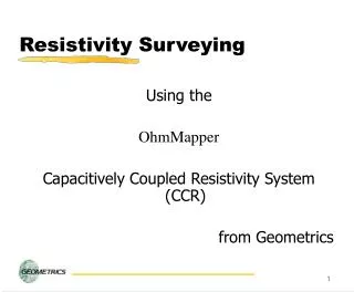
Basic well Logging Analysis – The Resistivity Logs. Hsieh, Bieng-Zih Fall 2009. General. Resistivity logs are electric logs which are used to: (1) determine hydrocarbon versus water-bearing zones, (2) indicate permeable zones, and (3) determine resistivity porosity.

Basic well Logging Analysis – The Resistivity Logs
E N D
Presentation Transcript
Basic well Logging Analysis – The Resistivity Logs Hsieh, Bieng-Zih Fall 2009
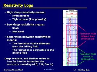
General • Resistivity logs are electric logs which are used to: • (1) determine hydrocarbon versus water-bearing zones, • (2) indicate permeable zones, and • (3) determine resistivity porosity. • By far the most important use of resistivity logs is the determination of hydrocarbon versus water-bearing zones.
General (Cont.) • Because the rock’s matrix or grain are non-conductive, the ability of the rock to transmit a current (電流) is almost entirely a function of water in the pores. • Hydrocarbons, like the rock’s matrix, are non-conductive; • therefore, as the hydrocarbon saturation of the pores increases, the rock’s resistivity also increases.
Calculate water saturation • A geologist, by knowing a formation’s water resistivity (Rw), its porosity (Φ), and a value for the cementation exponent (m), can determine a formation’s water saturation (Sw) from the Archie equation: • Sw= water saturation • Rw= resistivity of formation water, Rt = true formation resistivity as measured by a deep reading resistivity log • a = tortuosity factor, m = cementation exponent, n = saturation exponent (most commonly 2.0)
Two basic types of resistivity logs • The two basic types of logs in use today which measure formation resistivity are induction (感應式) and electrode (電極式) logs. • The most common type of logging device is the induction tool (Dresser Atlas, 1975)
Principle of the induction log 接收線圈 感應電流 地層環路 渦電流 發射線圈 通以電流
Induction log • An induction tool consists of one or more transmitting coils that emit a high-frequency alternating current of constant intensity. • The alternating magnetic field which is created induces secondary currents in the formation. • These secondary currents flow as ground loop currents perpendicular to the axis of the borehole, and create magnetic fields that induce signals to the receiver coils. • The receiver signals are essentially proportional to conductivity, which is the reciprocal of resistivity (Schlumberger, 1972). • conductivity = 1000/resistivity
Electrode log • A second type of resistivity measuring device is the electrode log. • Electrodes in the borehole are connected to a power source (generator), and the current flows from the electrodes through the borehole fluid into the formation, and then to a remote reference electrode. • Examples of electrode resistivity tools include: normal, Laterolog*, Microlog*, and spherically focused logs.
Resistivity Log • 電阻井測是量測電極(A)與另一端電極(M及N)之間的電位差,再利用歐姆定律計算而得地層電阻。
Choose an appropriate log survey • Induction logs should be used in non-salt-saturated drilling muds (i.e. Rmf > 3 Rw) to obtain a more accurate value of true resistivity (Rt). • Boreholes filled with salt-saturated drilling muds(Rmf≒Rw) require electrode logs, such as the Laterolog* or Dual Laterolog* with or without a Microspherically Focused Log*, to determine accurate Rt values.
Use Induction log or Laterolog Determining when use of an induction log is preferred over an electrode log such as the Laterolog*.
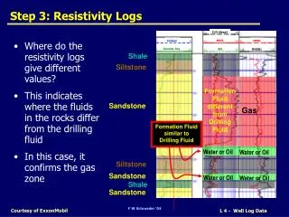
DEPTH OF RESISTIVITY LOG INVESTIGATION • Flushed Zone (Rxo) Invaded Zone (Ri) • Microlog* Short Normal## • Microlaterolog* Laterolog-8*## • Proxmity* Log Spherically focused Log*## • Microspherically Focused Log* Medium Induction Log • Shallow Laterolog* • Uninvaded Zone (Rt) • Long Normal • Lateral Log • Deep Induction Log • Deep Laterolog* • Laterolog-3* • Laterolog-7* • 電阻井測可依據其偵測的範圍(由井口深入地層的半徑大小),而分為淺測徑、中測徑及深測徑電阻井測,可以分別得到浸污區、過渡帶、及未浸污區的地層電阻值,進而求得地層的真電阻值。
Dual Induction Focused Log SFL (solid line) ILM (dotted-and –dashed line) ILD (dashed line)
Exercise • Find the true formation resistivity (Rt) and corrected resistivity of the flushed zone (Rxo) by using the Tornado Chart at depth 13590, 13600, 13610, 13620, 13630, and 13640.