SONET Architecture & SONET Layers
640 likes | 1.96k Vues
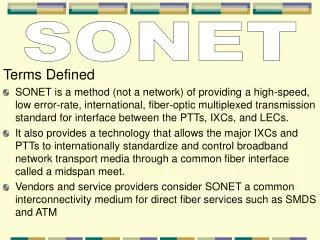
SONET Architecture & SONET Layers. SONET stand for Synchronous Optical NETwork. SONET. It is developed By ANSI ( A merican I nternational S tandard I nstitute ). It is a synchronous network using TDM multiplexing. All clocks in this system are locked to a master clock. SONET.

SONET Architecture & SONET Layers
E N D
Presentation Transcript
SONET • It is developed By ANSI(American International Standard Institute). • It is a synchronous network using TDM multiplexing. • All clocks in this system are locked to a master clock.
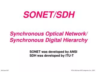
SONET • It is standardized multiplexing protocols that transfer multiple digital bit streams over optical fiber using Lasers or Light Emitting Diodes (LEDs). • Synchronous Optical Networking (SONET) and Synchronous Digital Hierarchy (SDH) is same.
Architecture • Signals • Devices • Connections
Signals • SONETdefines a hierarchy of electrically levels called Synchronous Transport Signal. • EachSTSlevel (STS-1 to STS-192) supports acertain data rate, specified in megabits per second. • Corresponding Optical Signals are called Optical Carriers (OCs). • SDHspecified similar system called Synchronous Transport Module (STM). See table next slide........
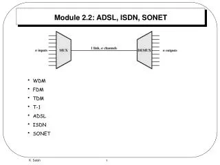
DEVICES • STS Multiplexers/ Demultiplexers mark the begining points and endpoints of SONET link. • Regeneratorextent the length of of the links. It is a repeater. • Add/Drop Mltiplexer (ADM) allow insertion and extraction of signals. • Terminalsis a device that uses the services of a SONET network.For example, in the internet, a terminal can be a router that needs to send packets to another router at hte other side of a SONET networks.
CONNECTIONs • Sectionsis the optical link connecting two neighbour devices: multiplexer to multiplexer, multiplexer or regenerators , regenerators to regenerators. • Linesis the portion of hte network betbeen two multiplexers: STS Multiplexers to Add/Drop Multiplexer, two Add/Drop Multiplexer, two STS Multiplexers • Pathsis the end-to-end portion of the network between two STS Multiplexers . In simlpe SONET of two STS multiplexers linkes directly to each other, the section, line and path are the same.
SONET Layers The SONET standard includes four functional layers: • Photonic • Section • Line • Path They corespond to both the physical and data link layers.
PathLayer • The path layer is responsible for the movement of a signal from its optical source to its optical destination. • At the optical source, the signal is changed from an electronic form into an optical from, multiplexed with other signals, and encapsulated in a frame. • At the optical destination the received frame is demultiplexed, and the individual optical signal are changed back into their electronic forms. • Path layer overhead is added at this layer. • STS multiplexed provide path layer functions.
Line Layer • Line layer is responsible for the movement of a signal across a physical line. • Line layer overhead is added to a frame at this layer. • STS multiplexers and add/drop multiplexers provide line layer functions.
Section Layer • Section layer is responsible for the movement of a signal across a physical line. • It handles framing, scrambling, and error control. • Section layer overhead is added to a frame at this layer.
Photonic Layer • Photonic Layer corresponds to the physical layer of the OSI model. • Its include the physical specifications for the optical fiber channel, the sensitivity of the receiver, multiplexing functions and so on. • SONET uses encoding with the presence of the light representing 1 and the absence of light representing 0.
Device-Layer Relationships • Following fig show the relationship between the devices used in SONET transmission and four layers of the standard. As we can see • STS multiplexer is a four-layer device. • An add/drop multiplexer is a three-layer device. • Regenerator is a two-layer device.