Download
1 / 56
560 likes | 674 Vues
In this comprehensive agenda from October 2001, we delve into the evolution of IP backbones and the emerging two-layer network architecture, emphasizing the convergence of packet (IP) and optical technologies. We explore the significance of GMPLS and the efficiency of using optical transport systems alongside traditional networking paradigms. Key topics include traffic engineering, restoration times, and the benefits of reduced complexity and enhanced scalability in network management. Discover the challenges and potential future directions for high-speed networks.

E N D
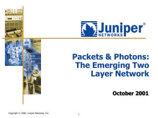
Packets & Photons: The Emerging Two Layer Network October 2001
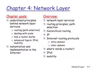
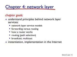
Agenda • History of IP Backbones • The Emerging Two Layer Network • Network Platforms • Standards and Forums • GMPLS
Core Router Core Router ATM Switch ATM Switch MUX MUX SONET/SDH ADM SONET/SDH ADM SONET/SDH DCS SONET/SDH DCS SONET/SDH ADM SONET/SDH ADM MUX MUX ATM Switch ATM Switch Core Router Core Router Typical IP Backbone (Late 1990’s) • Data piggybacked over traditional voice/TDM transport
Why So Many Layers? • Router • Packet switching • Multiplexing and statistical gain • Any-to-any connections • Restoration (several seconds) • ATM/Frame switches • Hardware forwarding • Traffic engineering • Restoration (sub-second) • MUX • Speed match router/ switch interfaces to transmission network • SONET/SDH • Time division multiplexing (TDM) • Fault isolation • Restoration (50mSeconds) • DWDM • Raw bandwidth • Defer new construction • Result • More vendor integration • Multiple NM Systems • Increased capital and operational costs
MUX becomes redundant IP trunk requirements reach SDH aggregate levels Next generation routers include high speed SONET/SDH interfaces Core Router (IP/MPLS) SONET/SDH DWDM IP Backbone Evolution Core Router (IP/MPLS) FR/ATM Switch MUX SONET/SDH DWDM (Maybe)
Removal of ATM Layer Next generation routers provide trunk speeds Multi-protocol Label Switching (MPLS) on routers provides traffic engineering Core Router (IP/MPLS) SONET/SDH DWDM IP Backbone Evolution Core Router (IP/MPLS) FR/ATM Switch MUX SONET/SDH DWDM (Maybe)
Removing the ATM Layer • Why Remove ATM? • Two networks to manage - IP and ATM • Cell tax • Lack of high-speed SAR interfaces • High density of virtual circuits • IP routing protocol stress Logical Topology
Agenda • History of IP Backbones • The Emerging Two Layer Network • Network Platforms • Standards and Forums • GMPLS
Collapsing Into Two Layers IP Service (Routers) Optical Core Optical Transport (OXCs, WDMs, SONET ?)
Collapsing Into Two Layers • IP router layer functions • Service creation • Multiplexing and statistical gain • Any-to-any connections • Traffic engineering • Restoration (10s ms) • Subscriber to transport speed matching • Delay bandwidth buffering and congestion control • Internet scalability IP Service (Routers) Optical Core Optical Transport (OXCs, WDMs, SONET ?)
Collapsing Into Two Layers • Optical transport layer functions • TDM and standard framing format • Fault isolation and sectioning • Restoration (10’s ms) • Survivability • Cost efficient transport of massive bandwidth (DWDM) • Long haul transmission distances • Metro transmission distances ???? IP Service (Routers) Optical Core Optical Transport (OXCs, WDMs, SONET ?)
The Emerging Two-Layer Network • Reduced cost • Transport layer visible to IP Services • Transport layer signaling is an open standard (RSVP & CR-LDP) Data Layer Routers IP Services Transport Layer OXC’s TDM’s WDM’s LH Transport • Reduced complexity • Network more scalable • Uniform admin & management of IP and transport layers
Agenda • History of IP Backbones • The Emerging Two Layer Network • Network Platforms • Standards and Forums • GMPLS
SONET/SDH Benefits • Rapid and predictable restoration • 10s of ms; depends on ring size • Simple to engineer • Standard framing and multiplexing (Time Division Multiplexing [TDM]) • Maintainability • Performance monitoring • Fault isolation and sectioning • Bandwidth management • Network management • Transparency • Voice, video or data traffic • Challenge • Remove complexity and keep benefits
SONET/SDH Benefits • Rapid and predictable restoration • 10s of ms; depends on ring size • Simple to engineer • Standard framing and multiplexing (Time Division Multiplexing [TDM]) • Maintainability • Performance monitoring • Fault isolation and sectioning • Bandwidth management • Network management • Transparency • Voice, video or data traffic • Challenge • Remove complexity and keep benefits TrafficQuickly ReroutedAfter Failure
SONET/SDH Limitations • Traditional SONET/SDH-based networks • Engineered for voice, not data • Slow to provision • Planning complexity • Grooming complexity • Delivery measured in weeks • Expensive to scale • Space, power, one wavelength per chassis • Inflexible • Static not dynamic bandwidth • Granularity – why not 5.5Gbps ? • Little interoperability at “control plane” • Customers forced to buy from one vendor • Stifles “best-in-class” deployment • Packet layer – no visibility into optical layer
Minimum qualifications Capable of switching IP datagrams: L3 forwarding Symmetric any-port-to-any-port switching speed Delay-bandwidth buffering, plus congestion control Internet scale IS-IS, OSPF, MPLS, BGP4 Today’s benchmark Wire-rate forwarding on all ports for 40-byte packets Performance independent of load Support of CoS queuing, shaping, and policing Traffic engineering Classification and filtering at wire rate What is an IP Router? A Device Which Moves IP Datagrams Across an Internetwork From Source to Destination ISO 7 Layer Model 7 - Application 6 - Presentation 5 - Session 4 - Transport 3 - Network 2 - Datalink 1 - Physical
What is an IP Router? Routing Algorithm Goals • Optimal routes • Calculate and select the best routes – many methods • Simplicity • Functional efficiency with low routing protocol overhead • Robust and stable • Predictable and correct functionality in a variable environment (hardware failure, high load, topology changes) • Rapid convergence • Slow route calculations cause loops and drops in service • Flexibility • Speed + accuracy to adapt to network changes (bandwidth, delays, queues, traffic levels, etc.) ISO 7 Layer Model 7 - Application 6 - Presentation 5 - Session 4 - Transport 3 - Network 2 - Datalink 1 - Physical
What is an IP Router? • Any-to-any connectivity • Internet scale routing allows anyone to connect to anyone (within or outside of own company) • Applications • Processing granularity to differentiate HTML from FTP • Multicast • Not possible with voice circuit switching technology • Internet radio, video on demand, push Web • Content sites • Directing Web traffic • Complementing cache servers • Security IP Service Creation ISO 7 Layer Model 7 - Application 6 - Presentation 5 - Session 4 - Transport 3 - Network 2 - Datalink 1 - Physical
Optical Cross-connects (OEO) SONET/SDH Digital Cross-connect (DXC) Also known as DigitalCross-connect Switch (DCS) DXC/DCS
STS-N DS-1 DS-3 STS-1 DS-3 DS-1 ATM ATM STS-N STS-1 ATM DS-1 DS-1 STS-N STS-N DS-3 DS-3 ATM DS-1 STS-N Optical Cross-connects (OEO) SONET/SDH Digital Cross-connect (DXC) Also known as DigitalCross-connect Switch (DCS) Electrical Switch Matrix
All Optical Cross-connects (OOO) All Optical Cross-connect (OXC) Also known as PhotonicCross-connect (PXC) OXC/PXC
l2 l4 l3 l1 l3 l2 l4 l1 All Optical Cross-connects (OOO) All Optical Cross-connect (OXC) Also known as PhotonicCross-connect (PXC) Optical Switch Fabric
Port 1 Port 3 Port 4 Port 2 What is an OpticalCross-connect? • Connects one port (l) to another port • Add/Drop function with certain l • Delivers high bandwidth • Quick to provision bandwidth ISO 7 Layer Model 7 - Application 6 - Presentation 5 - Session 4 - Transport 3 - Network l1 l2 2 - Datalink 1 - Physical l2 l1
Micro-electrical Mechanical Systems MEMs Used for many other applications From Lucent, Corning, Xros (Nortel), and others Currently 8 x 8 OXC 256 mirrors, long-term goal 1,024 OXC ADM uses seesaw MEMS Electrical controls Voltage applied to mirror; tilts on 2 axis + or – 6 degrees Switch times typically 10 to 25 ms Fibers Reflector Imaging Lenses MEMs tilting mirrors OXC/PXC Switching Mechanisms
OXC/PXC Switching Mechanisms • Liquid Crystal Light Valves • From Spectra Switch and Chorumtechnologies • Switch speed sub-millisecond • Future switch speed in nanosecond • 1 x 2 port switch • 2 x 2 Add/Drop • Electrical controls Liquid Crystal Cell ON Output 1 Input Polarizing Beam Splitter Polarizing Beam Splitter Liquid Crystal Cell
OXC/PXC Switching Mechanisms • Liquid Crystal Light Valves • From Spectra Switch and Chorumtechnologies • Switch speed sub-millisecond • Future switch speed in nanosecond • 1 x 2 port switch • 2 x 2 Add/Drop • Electrical controls Liquid Crystal Cell Input Polarizing Beam Splitter Polarizing Beam Splitter Output 2 OFF Liquid Crystal Cell
OXC/PXC Switching Mechanisms Bubbles • From Agilent • 32 x 32 or dual 16 x 32 ports • Suitable for • Wavelength Interchange Cross-connect (WIXC) • Wavelength Selective Cross-connect (WSXC) • Optical Add/Drop Multiplexers (OADM) • Inkjet + Silica Planar Lightwave Circuitry • Electrical controls • Bubbles created by heating “index matching fluid” • Switch times under 10 ms
Developing an All OpticalPacket Router • Needs • How do you read a photonic header? • The “pipeline” approach? • Switching and logic • Current technology not fast enough • Lithium Niobate devices have speed, but too much crosstalk • Photonic Bandgap Devices (optical equivalent to transistor) • Buffering/Memory • Optical buffers (fixed loop delays) exist, but are insufficient • Bi-stable lasers • Holographic memories • SEEDS (Self Electro-optic Effect Devices)
Agenda • History of IP Backbones • The Emerging Two Layer Network • Network Platforms • Standards and Forums • GMPLS
Operational Approaches:Overlay and Peer Models • Overlay model • Two independent control planes • IP/MPLS routing • Optical domain routing • Router is client of optical domain • Optical topology invisible to routers • Routing protocol stress – scaling issues • Does this look familiar? • Peer model • Single integrated control plane • Router and optical switches are peers • Optical topology is visible to routers • Similar to IP/MPLS model ?
Peer UNI Operational Approaches:The Hybrid Model • Hybrid model • Combines peer & Overlay • Middle ground of 2 extremes • Benefits of both models • Multi admin domain support • Derived from overlay model • Multiple technologies within domain • Derived from peer model
Standards and Industry Forums • Optical Internetworking Forum (OIF) • Industry forum • Kick-off meeting May 1998 • Standard OIF UNI based on IETF work (CR-LDP/RSVP) • Internet Engineering Task Force (IETF) • Driving GMPLS standards development • Initial application was MPlambdaS • Peer model and Hybrid model • Extend MPLS traffic engineering to the optical control plane • Rapid provisioning • Efficient restoration • ITU-T • Study Group 13 • Study Group 15
IETF • GMPLS now Hosted by CCAMP WG • Common Control And Measurement Plane • MPLS WG revised charter (without GMPLS) • Eleven main GMPLS building blocks • Internet Drafts • Current work includes extending existing control protocols (example, OSPF & ISIS) • New & future extensions considered • BGP4 • For cross AS, and Carrier of Carriers applications • LCAS • Link Capacity Adjustment Scheme protocol for SONET • SONET Virtual Concatenation (dynamic TDM circuit control) • Intent to submit work to ITU-T
ITU-T • Study Group 13 (SG13) • Focus: Multi-protocol & IP-based networks & their inter-working • Study Group 15 (SG15) • Focus: Optical & other transport networks • G.ASON – Automatically Switched Optical Network • Addresses the control layer for intelligent optical networks • Ambition to reference IETF standards
OIF Optical UNI Signaling OIF-UNI IETF-GMPLS • Uses procedures and messages defined for MPLS traffic engineering and GMPLS • Features • Runs in UNI-only mode (overlay model) • Optical path creation, modification, and deletion • Optical path status inquiry and response • Allows one protocol to support two different applications • OIF UNI: client bandwidth requests (hide optical topology) • GMPLS: service provider provisioning (expose optical topology) UNI UNI UNI UNI Optical Transmission Network UNI UNI
Agenda • History of IP Backbones • The Emerging Two Layer Network • Network Platforms • Standards and Forums • GMPLS
Traditional MPLS Applications Traffic Engineering Source Destination Layer 3 Routing Traffic Engineered LSP VPNs PE PE CPE CPE FT/VRF FT/VRF P Site 1 Site 3 FT/VRF CPE CPE P Site 2 Site 2 P P CPE CPE FT/VRF Site 1 Site 3 P FT/VRF FT/VRS FT/VRF PE PE
Generalized MPLS (GMPLS) • Traditional MPLS supports packet & cell switching • Extends MPLS to support multiple switching types • TDM switching (SDH/SONET) • Wavelength switching (Lambda) • Physical port switching (Fiber) • Peer model • Uses existing and evolving technology • Facilitates parallel evolution in the IP and optical transmission domains • Enhances service provider revenues • New service creation • Faster provisioning • Operational efficiencies
GMPLS Mechanisms • IGP extensions • Forwarding adjacency • LSP hierarchy • Constraint-based routing • Signaling extensions • Link Management Protocol (LMP) • Link bundling
IGP Extensions • OSPF and IS-IS extensions • Flood topology information among IP routers and OXCs • New link types • Normal link (packet) • Non-packet link (TDM, l, or fiber) • Forwarding adjacency (FA-LSP)
IGP Extensions • OSPF and IS-IS extensions • Flood topology information among IP routers and OXCs • New link types • Normal link (packet) • Non-packet link (TDM, l, or fiber) • Forwarding adjacency (FA-LSP)
Working Protection Working Protection IGP Extensions New Link Type sub-TLVs • Link protection • Protection capability • Attributes • None, 1+1, 1:N, or ring • Priority for a working channel 1:1 Protection 1:3 Protection
1:1 Protection Working Protection 1:3 Protection Working Protection IGP Extensions New Link Type sub-TLVs • Link descriptor • Characteristics of the link • Selected attributes • Link type • SONET, SDH, clear, Gig E, 10 Gig E • Minimum reservable bandwidth • Maximum reservable bandwidth • Attributes change over time • Provides a new constraint for LSP calculation • Shared Risk Link Group (SRLG) • List of the link’s SRLGs • Does not change over time
A node can advertise an LSP into the IGP Establishes LSP using RSVP/CR-LDP signaling IGP floods FA-LSP Link state database maintains conventional links and FA-LSPs A second node wanting to create an LSP can use an FA-LSP as a”link”in the path for a new, lower order LSP The second node uses RSVP/CR-LDP to establish label bindings for the lower order LSP Ingress Node (Low Order LSP) Egress Node (Low Order LSP) Ingress Node (High Order LSP) Egress Node (High Order LSP) Forwarding Adjacency SONET/SDH ADM SONET/SDH ADM FA-LSP ATM Switch ATM Switch
Ingress Node (Low Order LSP) Egress Node (Low Order LSP) Forwarding Adjacency • IGP attributes describing a forwarding adjacency • Local (ingress) and remote (egress) interface IP addresses • Traffic engineering metric • Maximum reservable bandwidth • Unreserved bandwidth • Resource class/color (administrative groups) • Link multiplexing capability (packet, TDM, l , or fiber) • Path information (similar to an ERO) SONET/SDH ADM SONET/SDH ADM FA-LSP Ingress Node (High Order LSP) Egress Node (High Order LSP) ATM Switch ATM Switch
LSP Hierarchy • Nesting LSPs enhances system scalability • LSPs always start and terminate on similar interface types • LSP interface hierarchy • Fiber Switch Capable (FSC) Highest • Lambda Switch Capable (LSC) • TDM Capable • Packet Switch Capable (PSC) Lowest PSC Cloud TDM Cloud LSC Cloud LSC Cloud TDM Cloud PSC Cloud FSC Cloud Fiber 1 Bundle Fiber n FA-PSC FA-TDM lLSPs lLSPs FA-LSC Explicit Label LSPs Time-slot LSPs Time-slot LSPs Explicit Label LSPs Fiber LSPs (Multiplex Low-order LSPs) (Demultiplex Low-order LSPs)
Extended IGP Routing Table Traffic Engineering Database (TED) Constrained ShortestPath First (CSPF) User Constraints Explicit Route RSVP Signaling Constraint-based Routing • Reduces the level of manual configuration • Input to CSPF • Path performance constraints • Resource availability • Topology information(including FA-LSPs) • Output • Explicit route for GMPLS signaling
GMPLS Signaling Extensions Label Related Formats (“Generalized Labels”) • Generalized label request • Link protection type (none, 1+1, 1:N, or ring) • LSP encoding type (packets, SONET, SDH, clear, DS-0, DS-1, …) • Generalized label object • Packet (explicit in-band labels) • Time slots (TDM) • Wavelengths (lambdas) • Space Division Multiplexing (fiber) • Suggested label • Label can be suggested by the upstream node • Speeds LSP setup times • Label set • Restrict range of labels selected by downstream nodes • Required in operational networks
PATH RESV SONET/SDH ADM SONET/SDH ADM GMPLS Signaling Extensions • Bi-directional LSPs • Resource contention experienced by reciprocal LSP using separate signaling sessions • Simplifying failure restoration in the non-PSC case • Lower setup latency • RSVP notification messages • Notify message informs non-adjacent nodes of LSP events • Notify-ACK message supports reliable delivery • Egress control • Terminate LSP at a specific output interface of egress LSR